Light guide system, lateral type backlight module and liquid crystal display (LCD)

A side-illuminated backlight and light introduction technology, applied in the field of liquid crystal display, can solve the problems affecting the optical quality of the backlight module, the small light-emitting angle of the light output end 21, increase the cost and the difficulty of production, etc., so as to improve the optical quality and reduce the brightness. The effect of uneven darkness and shortened propagation path

Inactive Publication Date: 2013-05-08
TCL CHINA STAR OPTOELECTRONICS TECH CO LTD
View PDF6 Cites 6 Cited by
  • Summary
  • Abstract
  • Description
  • Claims
  • Application Information

AI Technical Summary

Problems solved by technology

[0005] The main problem with the structure of the above-mentioned side-entry backlight module is that the light-emitting angle of the light-emitting end 21 of the optical fiber 20 is relatively small (usually within 60 degrees), and the light-emitting ends 21 of multiple optical fibers 20 are adjacent to the light-incoming surface of the light guide plate 30 31, if the distance between two adjacent light emitting ends 21 is large, there will be obvious uneven brightness and darkness on the light incident surface 31 of the light guide plate 30, thereby affecting the optical quality of the backlight module.
If the distance between two adjacent light-emitting ends 21 is reduced, it means that more optical fibers 20 need to be used, which will increase the cost and difficulty of manufacture

Method used


Image

  • Light guide system, lateral type backlight module and liquid crystal display (LCD)
  • Light guide system, lateral type backlight module and liquid crystal display (LCD)
  • Light guide system, lateral type backlight module and liquid crystal display (LCD)

Examples


Embodiment Construction

[0023] In order to better illustrate the technical means adopted by the present invention and its effects, a detailed description will be given below in conjunction with the embodiments of the present invention and the accompanying drawings, wherein the same reference numerals always represent the same components.

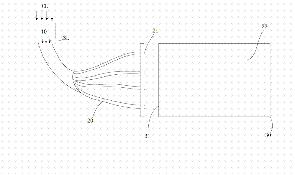
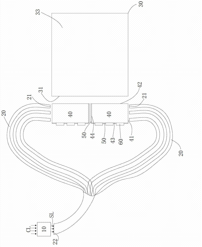
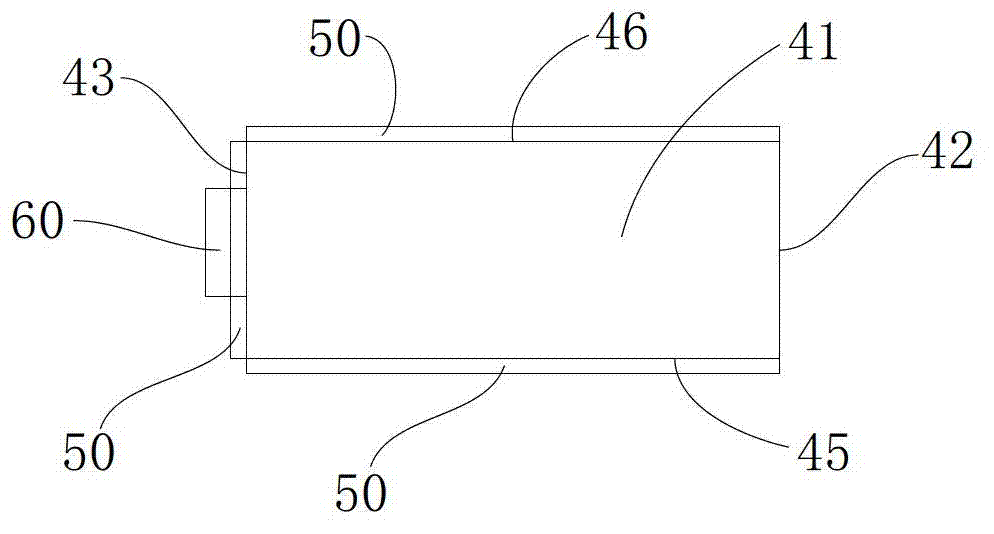
[0024] refer to figure 2 , image 3 , the light introduction system 1 includes: an ambient light collection system 10 , several optical fibers 20 , and two light guide strips 40 . Specifically, the ambient light collection system 10 faces and absorbs the ambient light CL, and then converts the ambient light CL into absorbed light SL. The wavelength of the light SL is within the wavelength range of visible light, that is, the absorbed light SL can be used as a backlight light source in the backlight module. Each optical fiber 20 has a light output end 21 and a light input end 22 , and the light input ends 22 of each optical fiber 20 are converged into a bundle an...


PUM


Abstract

The invention discloses a light guide system, a lateral type backlight module and a liquid crystal display (LCD). The light guide system comprises an ambient light collecting system, a plurality of light guide devices and at least two light guide bars. The ambient light collecting system faces towards ambient light, absorbs the ambient light and generates absorbed light. Each light guide device is provided with a light inlet end and a light outlet end, the light inlet end is close to the ambient light collecting system, and the absorbed light enters the light inlet end and is guided to the light outlet end. Each light guide bar comprises a light outlet lateral face, a light inlet lateral face and a second lateral face, wherein each light inlet lateral face is connected with the corresponding light outlet lateral face, and each second lateral face is opposite to the corresponding light inlet lateral face. The light outlet lateral faces are close to a light inlet face of a light guide panel, the second lateral face of a first light guide bar is arranged opposite to that of a second light guide bar, one part of the light outlet ends of the light guide devices are close to the light inlet lateral face of the first light guide bar, and the other part of the light outlet ends of the light guide devices are close to the light inlet lateral face of the second light guide bar.

Description

technical field [0001] The invention belongs to the field of liquid crystal display, and in particular relates to a light introduction system, a side-entry backlight module and a liquid crystal display. Background technique [0002] At present, the backlight source used in the backlight module of the TFT-LCD display is the common light-emitting diode (LED) or fluorescent tube, both of which use electricity as the driving energy source for light emission. However, in the entire backlight module The energy consumption of its backlight light source accounts for about 80%, and its energy consumption is very huge under long-term use. The currently used power generation categories are mainly divided into petroleum combustion power generation, coal combustion power generation and nuclear power generation, which will bring about environmental problems such as greenhouse effect and nuclear pollution. [0003] Ambient light in nature, such as sunlight, is a green and environmentally ...

Claims


Application Information

Patent Timeline
Patent Type & Authority Applications(China)
IPC IPC(8): F21V8/00F21S19/00G02F1/13357
CPCG02B6/0008G02B6/0028
Inventor 胡哲彰张光耀宁超樊勇
Owner TCL CHINA STAR OPTOELECTRONICS TECH CO LTD
Why Eureka
Try Eureka