Multifunctional mobile heat storing and discharging method and mobile heat supplying device

A heat supply device and transportation device technology, applied in the field of multifunctional mobile heat storage and release methods and mobile heat supply devices, can solve the problems of low transportation cost, small heat storage capacity, and large equipment investment

Active Publication Date: 2013-05-08
QINGDAO AOHUAN NEW ENERGY GRP CO LTD
View PDF5 Cites 10 Cited by
  • Summary
  • Abstract
  • Description
  • Claims
  • Application Information

AI Technical Summary

Problems solved by technology

At present, the most widely used is the hot water mobile heating device transported under atmospheric pressure within 100 °C. The main advantages of this device are low equipment cost and short heat storage and release time, but the biggest disadvantage is small heat storage capacity and high trans

Method used


Image

  • Multifunctional mobile heat storing and discharging method and mobile heat supplying device

Examples


Embodiment 1

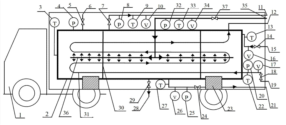
[0030] combine figure 1 , a mobile heating device, comprising a water storage tank 2 and a truck 1, the water storage tank 2 is a cylinder or an ellipsoid, made of carbon steel or stainless steel, and the outside of the water storage tank 2 is laid with a thickness of 10 cm layer of insulating material above. The water storage tank 2 is fixed on the truck 1 through the base 23, and the inside of the water storage tank 2 is provided with a heat exchange tube 31, and the inlet and outlet 12 of the heat exchange tube 31 are located outside the water storage tank 2. The inside of the water storage tank 2 is also provided with a distribution pipe 36, which is evenly opened with a plurality of nozzles, and the distribution pipe 36 is connected with an injection pipe 35 for accessing steam or hot water. The water storage tank 2 is connected with a cold water injection pipe 15, the water storage tank 2 is connected with a first pressure gauge 4 and a first temperature gauge 3, and is...

Embodiment 2

[0036] Embodiment 1 The heat storage and discharge method of the mobile heat supply device, comprising the following steps:

[0037](1) Heat storage process: inject cold water into the water storage tank 2, the liquid level of the cold water is higher than the heat exchange tube 31 and the distribution tube 36 inside the water storage tank 2, and the high temperature fluid is passed into the heat exchange tube 31 and the water storage tank The cold water in the tank 2 is subjected to indirect heat exchange, and high-temperature and high-pressure steam or hot water is injected into the cold water through the distribution pipe 36 for direct mixed heat exchange. Inject the high-temperature fluid into the medium, stop injecting high-temperature and high-pressure steam or hot water, and the heat storage of the water storage tank 2 ends;

[0038] (2) Heat release process: the steam outlet pipe 11 at the top of the water storage tank 2 releases steam at different temperatures and pre...


PUM


Abstract

The invention belongs to the technical field of mobile heat supplying, and particularly relates to a multifunctional mobile heat storing and discharging method and a mobile heat supplying device. The mobile heat supplying device comprises a water storage tank and a transporter, wherein the water storage tank is fixed on the transporter, a heat exchanging pipe is arranged in the water storage tank, and an inlet and an outlet of the heat exchanging pipe are both located outside the water storage tank, a distribution pipe is further arranged in the water storage tank, multiple spray nozzles are evenly formed in the distribution pipe, and a feeding pipe used for feeding steam or hot water is connected on the distribution pipe. A cold water feeding pipe is connected on the water storage tank, a first pressure gage, a first thermometer and a pressure reducing valve are connected on the water storage tank, a steam outlet pipe is connected with the top portion of the water storage tank, and a hot water outlet pipe is connected with the bottom portion of the water storage tank. The mobile heat supplying device is strong in heat storage capacity, has two heat exchanging modes, namely a direct heat exchanging mode and an indirect heat exchanging mode, can use waste heat and waste gas in various industries widely, and is especially suitable for using the waste heat in the industries to prepare clean saturated water with certain pressure at a certain temperature.

Description

technical field [0001] The invention belongs to the technical field of mobile heat supply, and in particular relates to a multifunctional mobile heat storage and discharge method and a mobile heat supply device. Background technique [0002] my country is rich in industrial waste heat resources, mainly including waste heat of high-temperature exhaust gas, waste heat of cooling medium, waste heat of waste steam and waste water, waste heat of high-temperature products and slag, waste heat of chemical reactions, etc. Waste heat resources account for about 17% to 67% of its total fuel consumption. The recovery rate reaches 60%, the waste heat utilization rate has a large room for improvement, and the energy-saving potential is huge. The characteristics of the current waste heat resources are: due to the periodicity, discontinuity or production fluctuation in the process of production, the waste heat is unstable. The nature of the waste heat medium is bad, such as the dust conten...

Claims


Application Information

Patent Timeline
IPC IPC(8): F24D15/02F24D19/10
CPCY02E60/14
Inventor 赵海龙
Owner QINGDAO AOHUAN NEW ENERGY GRP CO LTD
Why Eureka
Try Eureka