Photocatalytic water splitting

A technology of photocatalysis and photocatalysis, applied in the direction of physical/chemical process catalyst, inorganic chemistry, electrolysis process, etc., can solve problems such as difficult separation and not very effective

Inactive Publication Date: 2013-05-08
特温特大学
8 Cites 12 Cited by

AI-Extracted Technical Summary

Problems solved by technology

However, in the dispersion of these composite nanoassemblies, it will be difficult to separate the generated hydrogen and oxygen, and there i...

Method used

[0028] In an advantageous embodiment, the surface area of ​​the conductive isolation layer is increased. This increases the efficiency of water splitting, since efficient charge transfer is only possible for particles in contact with the metal. The surface area of ​​the conductive isolation layer can be increased, for example, by electron beam lithography (lithography), nanoimprint lithography or laser interference lithography, to generate submicron patterns (periodic) of protruding structures over a larger area. For example, a suitable structure is a periodic array of conductive nanopillars. Such nanopillars may have a diameter in the range of, for example, 10-100 nm, and a height in the range of 10-500 nm.
[0048] Figure 3 schematically shows an illustrative embodiment of the method and apparatus of the invention. In this figure, a container (1) is shown in which an electrically conductive isolation layer (2), mechanically supported by a perforated support (3), separates an oxygen evolution chamber (4) and a hydrogen evolution chamber (5). The oxygen evolution photocatal...

Abstract

The invention is directed to a method for photocatalytic water splitting, and to an apparatus for carrying out said method. The method of the invention comprises - oxidising water with an oxygen evolution photocatalyst by irradiation with light, causing an electron to be generated in the conduction band of the oxygen evolution photocatalyst and a hole to be generated in the valence band of the oxygen evolution photocatalyst; - reducing water with a hydrogen evolution photocatalyst by irradiation with light, causing an electron to be generated in the conduction band of the hydrogen evolution photocatalyst and a hole to be generated in the valence band of the hydrogen evolution photocatalyst; wherein said oxygen evolution photocatalyst is in contact with a first side of an electrically conductive separator layer and said hydrogen evolution photocatalyst is in contact with a second side of said electrically conductive separator layer, and wherein the electron from the conduction band of the photo-excited oxygen evolution photocatalyst recombines with the hole from the valence band of the photo-excited hydrogen evolution photocatalyst via charge transfer through the electrically conductive separator layer.

Application Domain

Electrolysis componentsHydrogen production +2

Technology Topic

Electrically conductiveConduction band +8

Image

  • Photocatalytic water splitting
  • Photocatalytic water splitting
  • Photocatalytic water splitting

Examples

  • Experimental program(1)

Example Embodiment

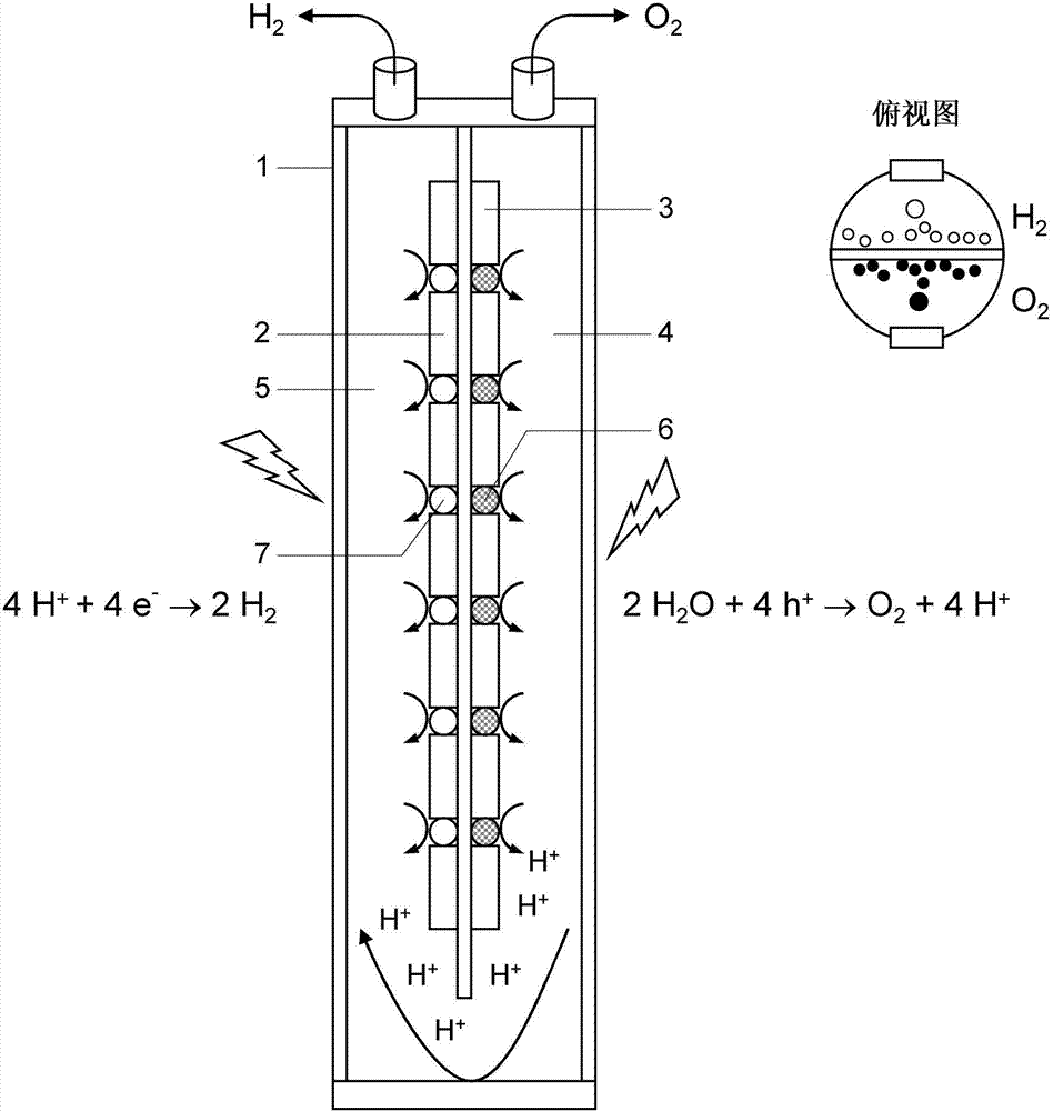
[0026]In one embodiment, the thin conductive isolation layer is mechanically supported by one or more perforated supports. This is particularly advantageous when the electrically conductive isolating layer is so thin that it has low mechanical stability itself. The perforated carrier may be provided on one or both surfaces of the conductive isolation layer. Since the support is perforated, it enables the photocatalyst to directly contact the conductive isolation layer, which is of course desirable in terms of efficient electron transfer.
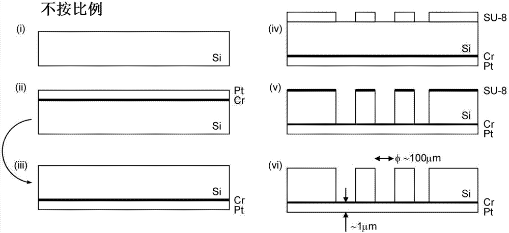
[0027] The perforated support has a thickness in the range of 50-1000 μm, preferably in the range of 100-750 μm, which can be determined by scanning and/or transmission electron microscopy. A suitable and practical carrier is, for example, a silicon carrier, such as a silicon wafer. If necessary, the carrier can be perforated, such as by a standard etching process (process, process). In many cases it is advantageous to produce an electrically conductive insulating layer on the carrier, and then optionally perforate the carrier. For example, a conductive isolation layer such as a metal layer can be deposited on a mechanical support such as a silicon wafer. Suitable deposition techniques include, for example, evaporation or sputtering. After the carrier has been turned over, the underlying conductive layer can be exposed by photolithographically perforating with standard photoresists such as SU-8, and holes are etched into the carrier. Then, the photoresist is optionally removed. exist figure 2 The fabrication process is exemplified in the embodiment of . exist figure 2 In an embodiment of the invention, the fabrication process starts in step (i) with a silicon wafer as a carrier. In step (ii), a metal film is evaporated or sputtered on top of the silicon wafer. The metal film serves as a conductive isolation layer. exist figure 2 In the embodiment shown, a platinum layer with a chromium adhesion layer is used. In step (iii), the silicon wafer is flipped. Thereafter, the openings are defined photolithographically in step (iv) using a standard photoresist, such as SU-8. After development, reactive ion etching (RIE) is applied to etch holes through the silicon wafer, step (v) with a very high aspect ratio (approximately 10). The photoresist can then be removed, for example, by washing with acetone, as in step (vi). like figure 2 The fabrication process shown in is illustrative only, and one skilled in the art will be able to derive similar fabrication methods based on the information provided herein.
[0028] In an advantageous embodiment, the surface area of ​​the electrically conductive isolation layer is increased. This increases the efficiency of water splitting, since efficient charge transfer is only possible for particles in contact with the metal. The surface area of ​​the conductive isolation layer can be increased, for example, by electron beam lithography (lithography), nanoimprint lithography or laser interference lithography, to generate submicron patterns (periodic) of protruding structures over a larger area. For example, a suitable structure is a periodic array of conductive nanopillars. Such nanopillars may have a diameter in the range of, for example, 10-100 nm, and a height in the range of 10-500 nm.
[0029] In this way, an electrically conductive isolating layer can be provided on the carrier, wherein the carrier is perforated (eg in a mesh structure) and the holes are in the form of holes penetrating the entire thickness of the carrier, thereby exposing the electrically conductive isolating layer.
[0030] When the photocatalyst material is subsequently deposited, preferably in the form of nanoparticles, the photocatalyst material is placed within the openings of the mechanical support so as to directly contact the exposed conductive isolation layer within the openings.
[0031] To minimize recombination of photoexcited electron-hole pairs, charge carriers that do not participate in the half-reactions involving water splitting must be efficiently transferred across the conductive isolation layer. On the other hand, opposite charges should remain on the photocatalyst material to facilitate the generation of oxygen and hydrogen. For oxygen evolution catalysts, for example, faster transfer of photoexcited electrons to the conductive spacer layer is desired, whereas hole transfer should be minimized. The conduction and valence band edges of photocatalyst materials often have distinctly different characteristics, which enable tuning of electron/hole transfer rates. For example, in TiO 2 The middle conduction band edge comes from the Ti(3d) valence state, while the valence band edge has O(2p) character. Ti(3d) orbitals hybridize at the interface with continuous bands of conductive isolating material (preferably metal), which can be achieved by bonding to TiO 2 The realization of unsaturated surface Ti sites of nanoparticles will lead to strong electronic coupling between these valence states, so photoexcited electrons from TiO 2 Quick transfer to conductive isolation material. The hybridization scheme can be controlled by the surface termination of the particle, in TiO 2 The experience ranges from Ti-rich, to stoichiometric, to oxygen-rich specific instances, which enables tuning of electron or hole transfer efficiency.
[0032] In an embodiment of the method of the invention, the electrically conductive isolating layer facilitates electron transfer but not proton transfer.
[0033] In addition to optimized electronic coupling, band alignment is an important issue because the valence and conduction bands of photocatalyst materials have to match the energy window determined by the redox potential generated by oxygen/hydrogen. match. In a preferred embodiment, since the photocatalyst nanoparticles are bound to the metal spacer, the metal/nanoparticle system should be considered in the design rather than the electronic properties of the individual nanoparticles. This opens an additional route to tuning energy levels, via interfacial band alignment rather than intrinsic electronic structure. This includes, for example, aligning the interfacial bands by surface modification of the nanoparticles and/or surface modification of the conductive isolation layer. Surface modification can be chemical, such as by adsorption of self-assembled monolayers or donor/acceptor molecules, and/or physical, such as by the use of nanoparticles with defined crystal faces.
[0034] In operation, protons generated in the oxygen evolution half-reaction of the oxygen evolution photocatalyst can diffuse from the oxygen evolution photocatalyst to the hydrogen evolution photocatalyst through the solution. At the hydrogen evolution photocatalyst, protons will be consumed according to the hydrogen generation half-reaction. Therefore, it is preferred that the oxygen evolution chamber is in direct fluid connection with the hydrogen evolution chamber, for example by not completely separating the oxygen evolution chamber and the hydrogen evolution chamber with an electrically conductive separation layer but maintaining an open connection between the two chambers. This allows for free diffusion from one chamber to the other and vice versa. Because protons can diffuse freely from the oxygen evolution chamber to the hydrogen evolution chamber, it is advantageous to not need to use the typically expensive membranes used in prior art systems for transporting the protons from the oxygen evolution chamber to the hydrogen evolution chamber.
[0035] Oxygen generated at the oxygen evolution photocatalyst will move upwards, where it can collect oxygen because its density is lower than that of water on one side of the conductive isolation layer. At the same time, the hydrogen gas generated at the hydrogen evolution photocatalyst will move upwards since its density is lower than that of water on the other side of the conductive isolation layer. Therefore, it is preferred that the method of the present invention is carried out in a vessel (or "chamber") containing water, wherein a conductive barrier separates the oxygen evolution chamber from the hydrogen evolution chamber. In order to enable free diffusion of protons from the oxygen evolution chamber to the hydrogen evolution chamber, the conductive isolation layer preferably does not completely extend to the bottom of the container. By extending the conductive isolation layer to the top of the container, the oxygen gas generated in the oxygen evolution chamber and the hydrogen gas generated in the hydrogen evolution chamber are prevented from mixing and reacting.
[0036] Light (preferably visible light) should be able to enter the photocatalyst in order to photoexcite the photocatalyst and provide the energy required for the water splitting reaction. This can be achieved by using a transparent material for the container and/or the conductive isolation layer. However, it is also possible to direct the light at the photocatalyst by using mirrors and/or concentrators.
[0037] In a further aspect, the invention relates to an apparatus, preferably for carrying out the water splitting method of the invention, said apparatus comprising:
[0038] - a container for containing the water to be photocatalytically decomposed,
[0039] - an electrically conductive insulating layer extending in the interior space of said container, said layer being in use in contact with water contained in said volume,
[0040] - a first surface of the electrically conductive isolating layer extending at least partly in water, provided with an oxygen evolution photocatalyst, and a second surface of the electrically conducting isolating layer extending at least partly in water, said second surface being preferably substantially the same as the first surface Instead, there are hydrogen evolution photocatalysts,
[0041] Wherein the conductive isolation layer is arranged in the container, so that light can reach the oxygen evolution photocatalyst and the hydrogen evolution photocatalyst, so that the hydrogen evolution photocatalyst can be used to oxidize water, and at the same time, the hydrogen evolution photocatalyst can be used to reduce water to decompose water.
[0042] Water to be photocatalytically decomposed is present in the container. A conductive insulating layer is provided in the interior space of the container. For example, this could be a layer extending down from the lid of the container and separating the container in two compartments. The conductive isolation layer is in contact with the water phase in the container (this means that only the photocatalyst on the surface of the conductive isolation layer is in contact with the water in the container).
[0043] A first surface of the conductive isolation layer is provided with an oxygen evolution photocatalyst to oxidize water, while a second surface (preferably the opposite side of the layer) is provided with a hydrogen evolution photocatalyst to reduce water. In order to oxidize water and reduce water, the portions of the first and second surfaces respectively provided with the oxygen evolution photocatalyst and the hydrogen evolution photocatalyst should extend in the water present in the container.
[0044] The conductive isolation layer is placed inside the container so that light (preferably visible light) can reach the oxygen evolution photocatalyst and the hydrogen evolution photocatalyst, so that water can be oxidized with the oxygen evolution photocatalyst, and at the same time the water is reduced with the hydrogen evolution photocatalyst, so that the water is decomposed . This can be achieved, for example, by making the container walls transparent to light (preferably visible light) (or parts thereof extending approximately parallel to the conductive isolation layer), allowing (visible) light to reach the oxygen evolution photocatalyst as well as the hydrogen evolution photocatalyst. In another embodiment, the container includes a reflector assembly arranged in the inner space of the container, so that light enters the container through the entrance in the container, and points to the conductive isolation layer, so that the light can reach the oxygen evolution photocatalyst and the hydrogen evolution photocatalyst.
[0045] In order to mechanically support the conductive isolation layer, one or more supports may be provided, including a receiving portion for containing the oxygen evolution photocatalyst and/or the hydrogen evolution photocatalyst. Preferably, the one or more supports are perforated supports, and the perforations form the receiving part of the oxygen evolution photocatalyst and/or the hydrogen evolution photocatalyst. The carrier may be provided on either side of the conductive isolation layer, or on both sides of the conductive isolation layer.
[0046] In a preferred embodiment, the first upper end of the container includes an oxygen outlet fluidly connected to an oxygen evolution chamber and a hydrogen outlet fluidly connected to a hydrogen evolution chamber defined by at least a portion of the peripheral wall of the container and a conductive barrier, wherein in the container The second lower end of the first end, preferably opposite to the first end, provides an opening between the conductive isolation layer and the bottom wall of the container to provide a fluid connection between the oxygen evolution chamber and the hydrogen evolution chamber. The opening between the electrically conductive separating layer and the bottom wall of the vessel then enables the transfer of protons from the oxygen evolution chamber to the hydrogen evolution chamber, for example by diffusion.
[0047] The conductive isolation layer preferably has a thickness measured by SEM in the range of 100-5000 nm, more preferably in the range of 200-3000 nm.
[0048] image 3 An illustrative embodiment of the method and the device of the invention are shown schematically. In this figure, a container (1) is shown in which an electrically conductive isolation layer (2), mechanically supported by a perforated support (3), separates an oxygen evolution chamber (4) and a hydrogen evolution chamber (5). The oxygen evolution photocatalyst nanoparticles (6) are in direct contact with the conductive isolation layer (2) in the oxygen evolution chamber (4), while the hydrogen evolution photocatalyst nanoparticles (7) are in direct contact with the conductive isolation layer (2) in the hydrogen evolution chamber (5). direct contact. Since the conductive isolation layer (2) does not extend to the bottom of the container (1), the water in the oxygen evolution chamber (4) is in fluid connection with the water in the hydrogen evolution chamber (5), enabling protons to diffuse from the oxygen evolution photocatalyst to hydrogen evolution photocatalysts. After photoexcitation of the oxygen evolution and hydrogen evolution photocatalysts, the oxygen evolution half reaction of water splitting occurs in the oxygen evolution chamber (4), and the hydrogen generation half reaction of water splitting occurs in the hydrogen evolution chamber (5). A top view of the vessel showing the generated oxygen and hydrogen gases are spatially separated by a conductive barrier, which makes it easy to collect these gases individually.
[0049]In operation, light irradiation induces photoexcitation of the oxygen evolution photocatalyst (6) and hydrogen evolution photocatalyst (7). The photogenerated holes in the valence band of the oxygen evolution photocatalyst (6) are used for the oxidation of water in the oxygen evolution chamber (4), while the photogenerated electrons in the conduction band of the hydrogen evolution photocatalyst (7) are used for the hydrogen evolution Reduction of water in chamber (5). The conductive isolation layer (2) allows photogenerated electrons in the conduction band of the oxygen evolution photocatalyst (6) to effectively recombine with photogenerated holes in the valence band of the hydrogen evolution photocatalyst (7). Meanwhile, the conduction band isolation layer (2) acts as a barrier for photocatalytically generated oxygen and hydrogen.
[0050] Figure 4 The schematic diagram in further illustrates the method and apparatus of the present invention.

PUM

no PUM

Description & Claims & Application Information

We can also present the details of the Description, Claims and Application information to help users get a comprehensive understanding of the technical details of the patent, such as background art, summary of invention, brief description of drawings, description of embodiments, and other original content. On the other hand, users can also determine the specific scope of protection of the technology through the list of claims; as well as understand the changes in the life cycle of the technology with the presentation of the patent timeline. Login to view more.
Why Eureka
Try Eureka