Laser welding composite material for solar collector

A composite material and laser welding technology, which is applied to the parts, anodic oxidation, and absorbing elements of solar collectors, can solve the problems that the efficiency is still improved

Active Publication Date: 2013-05-15
阿兰诺德股份有限两合公司
View PDF11 Cites 5 Cited by
  • Summary
  • Abstract
  • Description
  • Claims
  • Application Information

AI Technical Summary

Problems solved by technology

[0004] In this way, compared with other similar methods, the laser welding method has achieved higher efficiency, but there is still room for improvement in this efficiency.

Method used


Image

  • Laser welding composite material for solar collector
  • Laser welding composite material for solar collector
  • Laser welding composite material for solar collector

Examples


Embodiment Construction

[0053] For the following description, it needs to be emphasized that the present invention is not limited to these embodiments, and therefore is not limited to all or more features in the described combination of features; in fact, every single sub-feature in any embodiment When separated from all other sub-features described together, whether it exists alone or in combination with any feature in another embodiment, it still has the meaning of the invention.

[0054] In the different figures, identical components, or in particular layers that perform the same function, are assigned the same reference symbols and are therefore generally only described once in the following text.

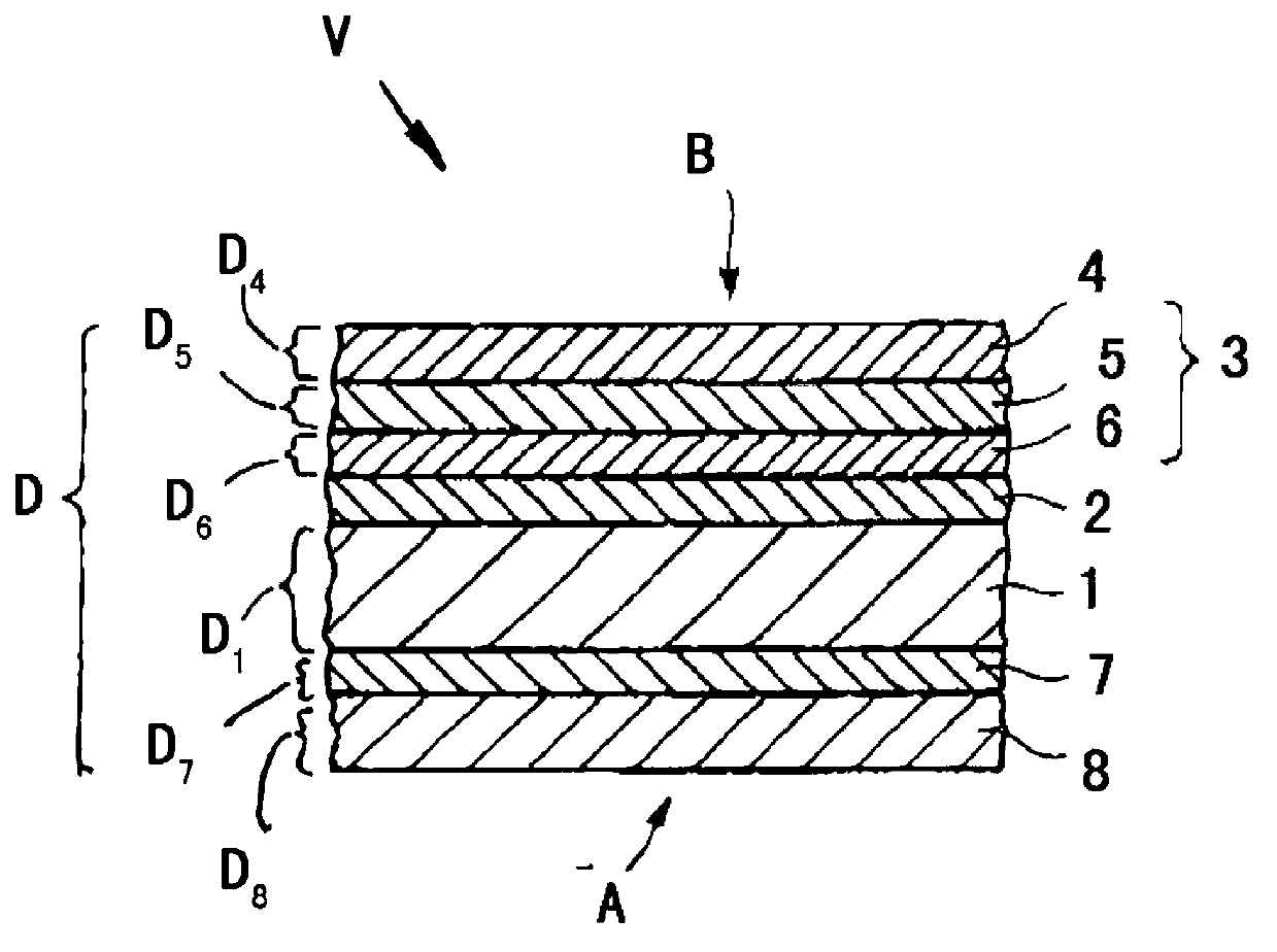
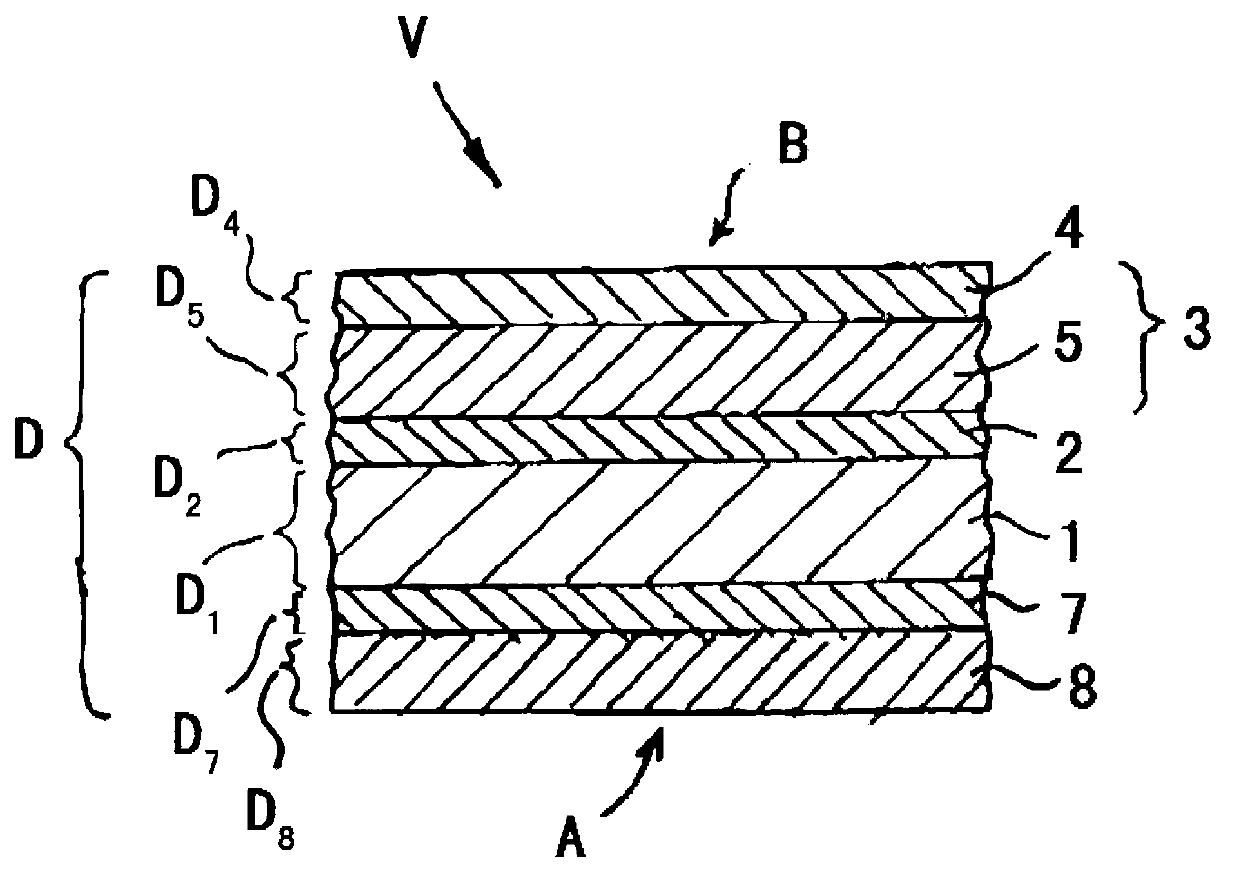
[0055] first as figure 1 As shown, a first embodiment of a laser-weldable composite material V according to the invention, which can be used in particular for the production of solar collector elements, comprises a metal base body 1 in the form of a strip. The base body has a first side A and a secon...


PUM

PropertyMeasurementUnit
Thicknessaaaaaaaaaa
Thicknessaaaaaaaaaa
Thicknessaaaaaaaaaa

Abstract

The composite material (V) has a band-shaped metal (1) with high reflectivity for laser radiation beam having lower side (A) on which a ceramic coating (7) is formed. The metallic layer (8) is formed over the ceramic coating. The thickness (D7) of the ceramic coating and the thickness (D8) of metallic layer are dimensioned in accordance with DIN 5036, such that specific total reflectance at an angle of incidence ranges from 65-80[deg] of the incident laser light beam (L) with a wavelength of 1064 nm on lower side of metal, is lesser than 60%.

Description

technical field [0001] The invention relates to a laser-weldable composite material, in particular for solar collector elements, comprising a strip-shaped material made of highly reflective properties for laser rays ( ) of the metal substrate ( ), the substrate has a first face and a second face, wherein at least the first face has a ceramic coating. Background technique [0002] European Patent Application EP 2 239 086 A1 discloses such a composite material. In this patent application document is described a known method for laser welding composite materials to a workpiece, in particular for the manufacture of solar collector elements, wherein the composite material comprises a performance of a strip-shaped substrate made of metal, the strip-shaped substrate has a first face and a second face, and has a ceramic coating on at least the first face, in addition, in order to form a weld, the laser beam needs to be projected at least to The ceramic coating is disposed on th...

Claims


Application Information

Patent Timeline
IPC IPC(8): B32B15/04B32B18/00F24J2/48
CPCF24J2/484Y02E10/40F24J2/00C25D11/04F24J2/485B32B15/04F24S70/16F24S70/225
Inventor 弗朗克·滕普林迪米特里奥斯·佩罗斯
Owner 阿兰诺德股份有限两合公司
Why Eureka
Try Eureka