Compression ratio adjustment method for prepressing spiral structure

A pre-pressing and spiral technology, applied in the field of pre-pressing spirals, can solve problems such as changes in internal parameters of welding deformed spirals, difficult operation of cutting spiral pre-pressing blades, complicated disassembly of a spiral, etc., to achieve difficult resolution, reasonable design, and improved production Effect

Inactive Publication Date: 2013-05-15
LUOYANG MINING MACHINERY ENG DESIGN & RES INST
View PDF8 Cites 2 Cited by
  • Summary
  • Abstract
  • Description
  • Claims
  • Application Information

AI Technical Summary

Problems solved by technology

However, this method has the following disadvantages: 1) When the screw equipment is small, it is easier to disassemble the screw blades, and the form of cutting and pre-pressing blades is more operable, but when the screw equipment is larger, it is equivalent to disassembling the screw once. It is complicated, and it is difficult to adjust the compression ratio in the form of cutting spiral pre-compression blades; 2) In this adjustment method, if the compression ratio needs to be increased, it is necessary to re-weld the cut thing, and its welding deformation is easy to cause Variations in the internal parameters of the helix, and the welding operation is also very difficult

Method used


Image

  • Compression ratio adjustment method for prepressing spiral structure

Examples


Embodiment 1

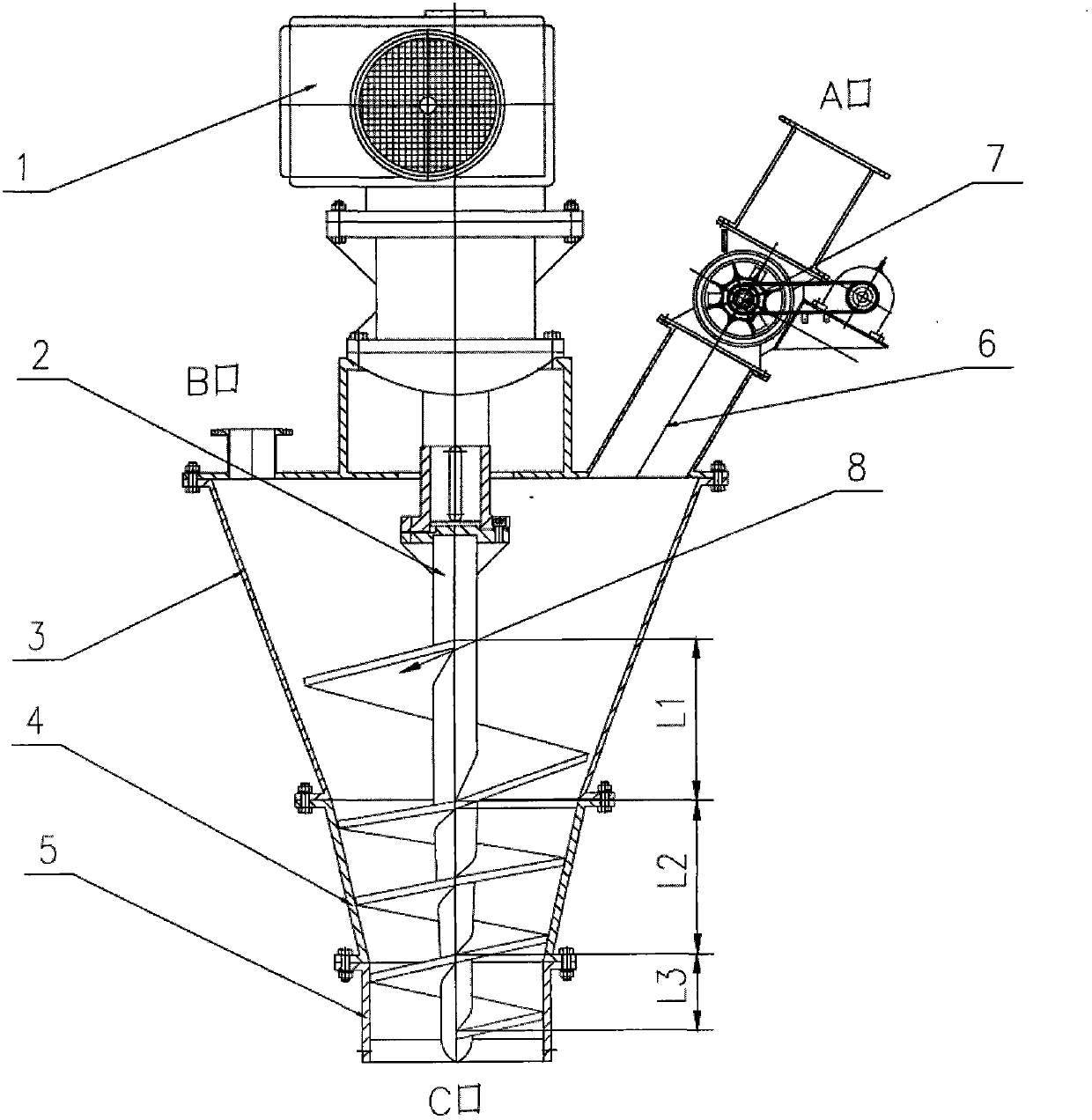
[0044] As shown in the figure; the pre-pressing silo 4 is set under the pre-pressing silo 3 of the spiral structure, the guide hopper 5 is set under the pre-pressing silo 4, the cover is set above the biting hopper 3, and the middle part of the cover is set The transmission support, the shaft hole is reserved in the center of the cover, the screw transmission system 1 is set above the transmission support, and the screw shaft 2 is set below the screw drive system 1; the screw shaft 2 is set in the shaft hole reserved in the center of the cover, and the outside of the screw shaft 2 Set the spiral blade 8, set the dust removal port B on one side above the cover of the bite bin 3, and set the feed pipe 6 on the other side above the cover of the bite bin 3; set the feed port A above the feed pipe 6, An adjustable feeding device 7 is arranged in the middle section of the feeding pipe 6 .

Embodiment 2

[0046] As shown in the figure; a large mouth is set above the bite bin 3, and a small mouth is set under the pre-press bin 4. The bite bin 3 and the pre-press bin 4 are set with a trumpet shape with a large top and a small bottom. The small opening of the warehouse 4 corresponds to the guide hopper 5; the bite hopper 3, the pre-pressing hopper 4, and the guide hopper 5 are provided with a screw blade 8 coaxial with the screw shaft 2, and the upper part of the screw blade 8 corresponds to the feed pipe 6 The biting spiral leaf segment L1 in the biting material bin 3 is provided with a large pitch, the pre-pressing spiral leaf segment L2 in the pre-pressing bin 4 is provided with a small pitch, and the upper end of the biting material spiral leaf segment L1 is connected to the lower end of the pre-pressing spiral leaf segment L2 The pitch of the helical blade 8 between the upper and lower gradient settings, the upper width of the helical blade 8 and the lower narrow setting; the ...

Embodiment 3

[0048] When working, the screw drive system 1 drives the screw blade 8 on the screw shaft 2 to rotate and convey the material, and the input amount of the material is synchronized with the processing amount of the next equipment; the material is input into the feed pipe 6 through the feed port A, and the feed pipe 6 The material is input into the bite bin 3 through the adjustable feeding device 7 in the middle section; the output volume of the adjustable feeding device 7 is adjusted according to the setting of the compression ratio; the setting of the compression ratio is: the compression ratio is 2.5 Adjust between -1.05:1, the compression of the material is through the pitch between the screw blades 8 from large to small and the change of the screw blade 8 from wide to narrow, and the screw blade 8 squeezes the material downward through rotation.


PUM


Abstract

The invention discloses a compression ratio adjustment method for a prepressing spiral structure. A spiral transmission system drives spiral blades on a spiral shaft to convey materials in rotating mode, and an input amount of the materials is synchronous with a processing amount of a next segment device; the materials are input into a material inlet pipe through a feed inlet A and input into a material biting bin through an adjustable feeding device in the middle segment; an output amount of the adjustable feeding device regulates a conveying amount according to setting of a compression ratio; and the setting of the compression ratio includes that the compression ratio is regulated between 2.5:1 and 1.05:1, the materials are compressed due to the fact that thread pitches of the spiral blades are changed from big to small and the spiral blades are changed from wide to narrow, and the materials are compressed by the spiral blades in a rotary mode. The compression ratio adjustment method for the prepressing spiral structure is designed to be reasonable, material filling rates among the blades are regulated, the spiral blades are not required to be detached, the compression ratio of the prepressing spiral structure is regulated automatically, the compression ratio adjustment method for the prepressing spiral structure is easy to operate, energy-saving, and consumption-reducing.

Description

technical field [0001] The invention relates to a pre-compression screw for conveying industrial granular materials, in particular to a method for adjusting the compression ratio of the pre-compression screw structure. Background technique [0002] With the rapid development of my country's industrial technology, the demand for screw conveying technology in the process of conveying various fine particles and powdery materials is also increasing, especially in the field of supporting molding. A major problem in the development of high-pressure molding technology for fine particles and powdery materials. [0003] At present, there are various forms of screw conveying technology at home and abroad. According to different needs, there are pre-pressed conveying screws, and there are only quantitative conveying screws. There are horizontal pre-pressed conveying screws and vertical pre-pressed conveying screws. However, due to the different properties of materials and changes in th...

Claims


Application Information

Patent Timeline
Patent Type & Authority Applications(China)
IPC IPC(8): B65G33/14B65G33/24
Inventor 郝兵戚天明崔郎郎张光宇史宝龙成友斌
Owner LUOYANG MINING MACHINERY ENG DESIGN & RES INST
Why Eureka
Try Eureka