Light emitting diode (LED) lamp wick and lighting device with LED as light source

A technology of light-emitting diodes and lighting devices, which is applied to lighting devices, components of lighting devices, cooling/heating devices of lighting devices, etc., and can solve problems such as declining user willingness to use, rising manufacturing costs, and unfavorable popularization and promotion of LED lighting devices.

Inactive Publication Date: 2013-05-15
赵依军 +1
View PDF1 Cites 11 Cited by
  • Summary
  • Abstract
  • Description
  • Claims
  • Application Information

AI Technical Summary

Problems solved by technology

[0007] However, it should be pointed out that the implementation of the above-mentioned heat dissipation design scheme is often at the expense of rising manufacturing costs, which will lead to a decline in users' willingness to use, which is not conducive to the popularization and promotion of LED lighting devices.

Method used


Image

  • Light emitting diode (LED) lamp wick and lighting device with LED as light source
  • Light emitting diode (LED) lamp wick and lighting device with LED as light source
  • Light emitting diode (LED) lamp wick and lighting device with LED as light source

Examples


no. 1 example

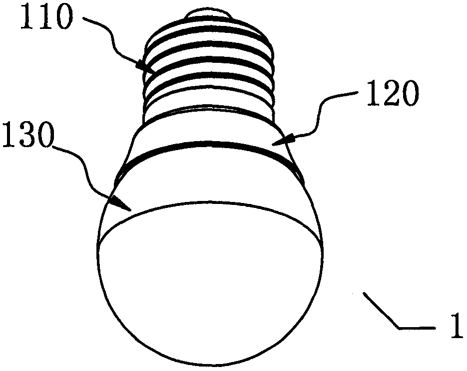
[0201] figure 1 It is a schematic diagram of a lighting device using a light emitting diode as a light source according to the first embodiment of the present invention, which shows the structure of the lamp housing.

[0202] Such as figure 1 As shown, the lamp housing 1 of the lighting device according to this embodiment includes a lamp cap 110 and a heat sink 120 ( figure 1 Cup-shaped parts in the middle) and the lampshade 130. In this embodiment, the lamp holder 110 can adopt a screw-like screw interface form similar to ordinary incandescent lamps and energy-saving lamps, so as to provide electrical connection with an external power supply (for example, 220 volt AC power supply) for the lighting device, but a rotating card can also be used The heat sink 120 is arranged between the lamp cap 110 and the lampshade 130. It can be made of various insulating and heat-dissipating materials, such as ceramic materials or thermally conductive insulating polymer composite materials. On th...

no. 2 example

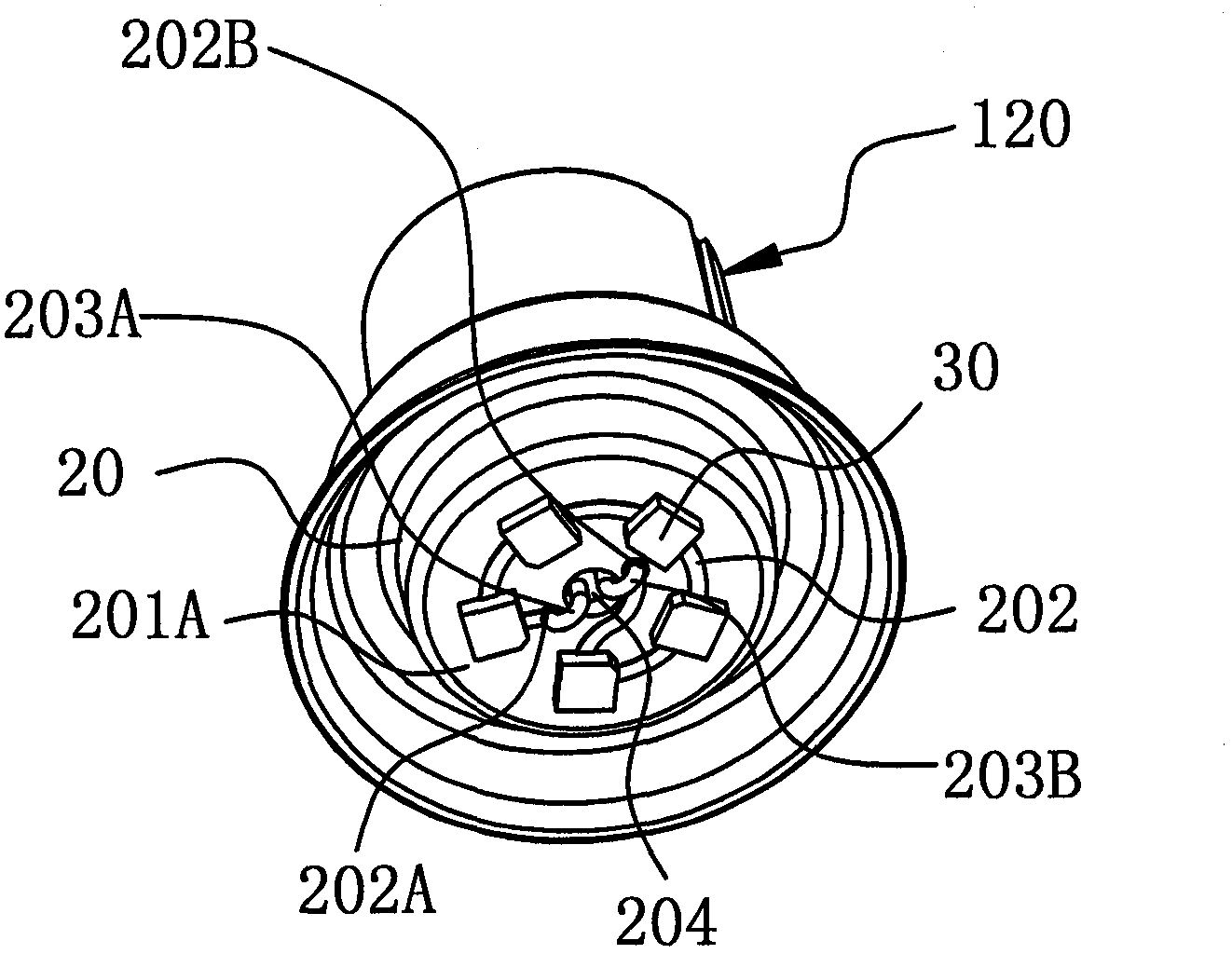
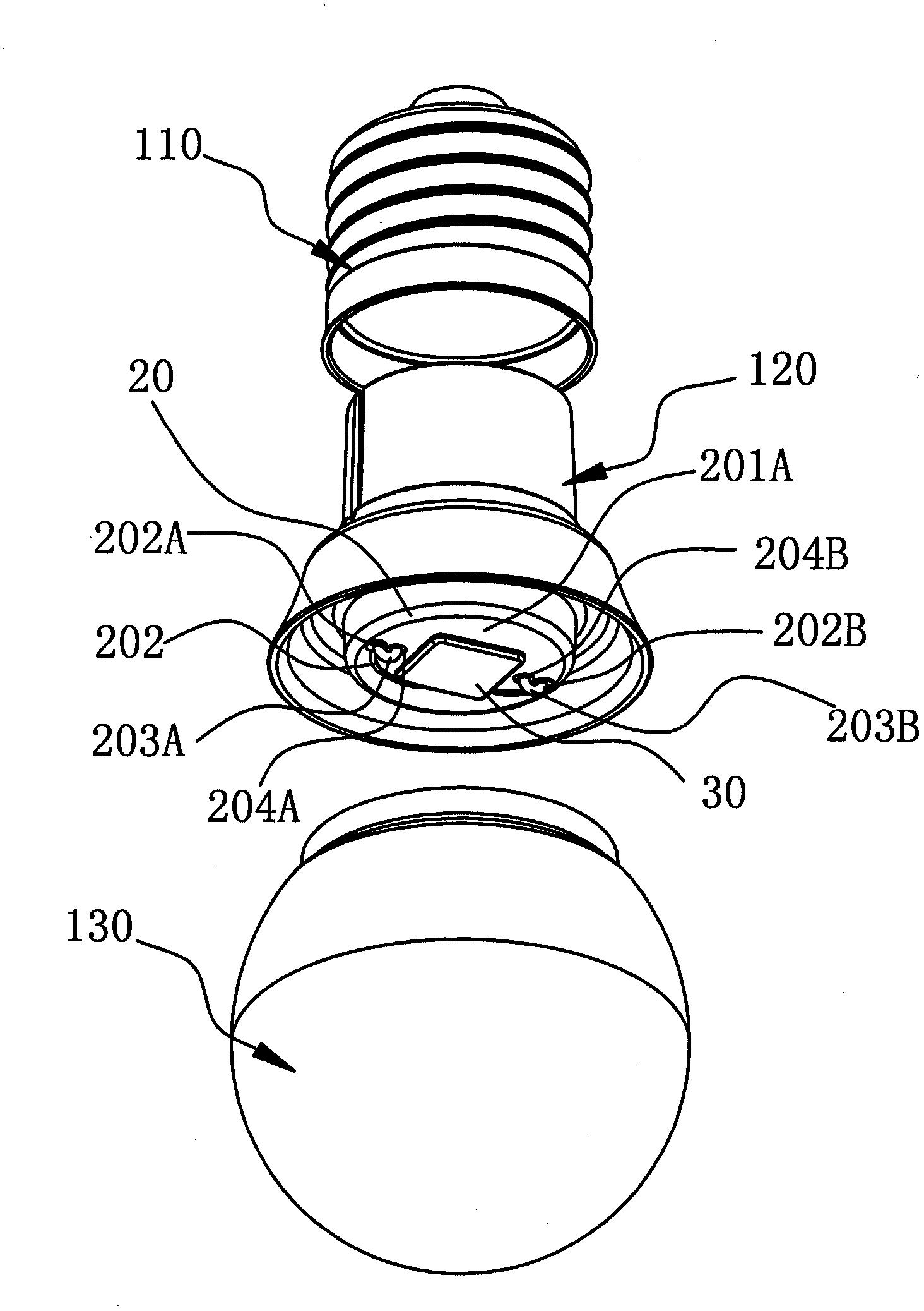
[0215] image 3 It is a schematic diagram of a lighting device using light emitting diodes as a light source according to the second embodiment of the present invention, which adopts an arrangement of multiple light emitting diode units as light sources. For simplicity, image 3 Only components such as heat sinks and substrates made of insulating and thermally conductive materials or metal materials are shown.

[0216] Such as image 3 As shown, the heat sink 120 ( image 3 The inner cavity of the bowl-shaped component) is also provided with a substrate 20 perpendicular to its axial direction. The substrate can also be integrally formed with the heat sink 120 or fixed together with an adhesive or a notch. The main difference between this embodiment and the previous embodiment is that a plurality of LED monomers 30 connected in series are provided on the surface of the substrate 20 here.

[0217] Specifically, see image 3 , The five LED monomers 30 are adhered on the surface 201A o...

no. 3 example

[0220] Figure 4 It is a schematic diagram of a lighting device using a light emitting diode as a light source according to the third embodiment of the present invention.

[0221] Such as Figure 4 As shown, the lamp housing 1 of the lighting device according to this embodiment also includes a lamp cap 110, a heat sink 120 and a lamp cover (not shown). This embodiment and the above Figure 1-3 The main difference of the illustrated embodiment lies in the structure of the heat sink that carries the light source and various functional circuits, which will be further described below.

[0222] A cylindrical body 40 is arranged inside the lamp housing. The cylindrical body 40 extends along the longitudinal axis of the lamp housing and is also made of insulating and thermally conductive material. It can be integrally formed with the heat sink 120, or as Figure 4 A supporting base 401 is shown, and the supporting base 401 and the heat sink 120 are fixed together by means of thermally con...


PUM


Abstract

The invention relates to the semiconductor lighting technology, in particular to a light emitting diode (LED) lamp wick and a lighting device with an LED as a light source. The purpose is to provide the LED lamp wick suitable for being fitted to a lamp housing to provide a lighting device which is good in heat dissipating effect and low in production cost. One more purpose is to provide the lighting device with the LED as the light source, and the lighting device with the LED as the light source has the advantages of being both good in heat dissipating effect and low in production cost.

Description

Technical field [0001] The invention relates to semiconductor lighting technology, in particular to a light-emitting diode wick and a lighting device using the light-emitting diode as a light source. Background technique [0002] The light-emitting diode (LED) currently used as a light source in lighting devices is a solid-state semiconductor device. Its basic structure generally includes a leaded bracket, a semiconductor chip set on the bracket, and a packaging material (such as Fluorescent silica gel or epoxy resin). The above semiconductor wafer contains a PN structure. When a current passes, electrons are pushed to the P area, where the electrons recombine with holes, and then emit energy in the form of photons. The wavelength of the light is determined by the material that forms the PN structure. decided. Compared with incandescent lamps and fluorescent energy-saving lamps, light-emitting diodes have many advantages such as environmental protection, recyclability, high lum...

Claims


Application Information

Patent Timeline
Patent Type & Authority Applications(China)
IPC IPC(8): F21S2/00F21V29/00F21V23/00F21Y101/02
CPCH05K1/00F21V3/02F21S2/00F21Y2105/001F21Y2111/005F21K9/13F21V19/00F21V29/00F21K9/135F21Y2111/007F21Y2101/02F21V23/005F21K9/23F21K9/232F21K9/238F21Y2105/10F21Y2107/30F21Y2107/40F21Y2115/10
Inventor 赵依军李文雄
Owner 赵依军
Why Eureka
Try Eureka