Accurate calibration method of film coating rate and application thereof

A calibration method and rate technology, applied in the direction of optical devices, measuring devices, instruments, etc., to achieve the effect of simple method, poor signal-to-noise ratio, and improved calibration accuracy

Inactive Publication Date: 2013-05-15
CHANGZHOU INST OF OPTOELECTRONICS TECH +4
View PDF3 Cites 7 Cited by
  • Summary
  • Abstract
  • Description
  • Claims
  • Application Information

AI Technical Summary

Problems solved by technology

[0007] The purpose of the present invention is to overcome the principle limitations and insurmountable difficulties of the traditional method, and provide a simple and quick method for accurately calibrating the coating rate of various dielectric thin films. This method can maintain...

Method used


Image

  • Accurate calibration method of film coating rate and application thereof
  • Accurate calibration method of film coating rate and application thereof
  • Accurate calibration method of film coating rate and application thereof

Examples


Embodiment 1

[0043] The accurate calibration method of the coating rate in this embodiment takes the film 2 to be measured as SiO2 (refractive index is about 1.46) as an example.

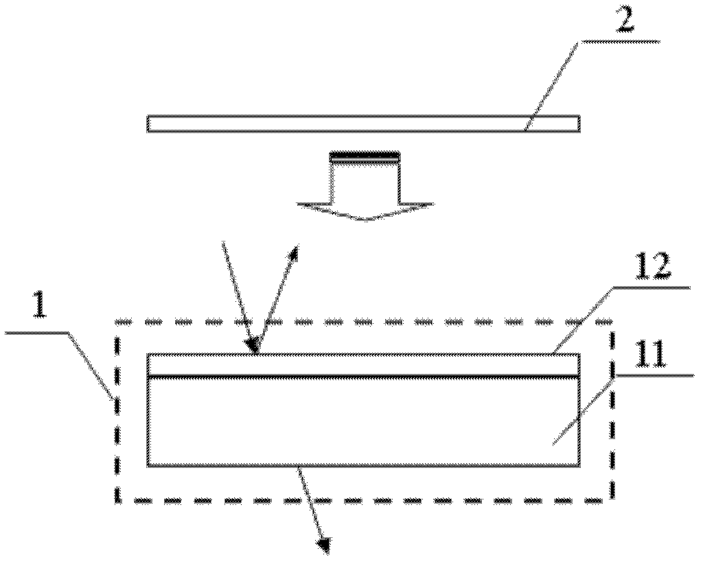
[0044] Step ①: Prepare standard substrate 1; see figure 1 , the standard substrate 1 includes a substrate 11 and an interference film 12; the preparation method is: on the substrate 11, a layer of interference film 12 sufficient to form interference is introduced; the refractive index of the substrate 11 of the standard substrate 1 is different from that of the interference film 12 , and the greater the difference in refractive index, the better. The thickness of the interference film 12 of the standard substrate 1 makes the interference film 12 produce only one-order interference in the 400-1000nm band, at this time the interference peak can obtain the largest shift, and the change caused by the thickness is the most obvious. When the thickness of the interference film is constant, the smaller the refractive i...

Embodiment 2

[0063] In this embodiment, SiO2 plating is still taken as an example, and the basic calibration method is as in Example 1, except that the SiO2 thin film of the rate to be measured is plated for 5 minutes. front and rear transmission spectra as Figure 9 As shown, the calculation can be obtained: the interference peak displacement is 81.9nm, the thickness fitting result is 56.1nm, and the plating rate is 11.2nm / min. The result of this embodiment shows that when the film to be tested is thicker or the coating rate is higher, the application method of the present invention is still effective.

Embodiment 3

[0065] This embodiment still takes the SiO2 plating as an example, the basic calibration method is as in Example 1, the difference is: the SiO2 film of the rate to be measured is plated by a vacuum evaporation coating system for 10 seconds, and the plating is carried out according to the following steps:

[0066] 1) Clean the tungsten wire, slide glass and crucible.

[0067] 2) Check the fixation of the tungsten wire and the position of the electrode in the bell jar, add quartz sand into the crucible, and put it into the crucible.

[0068] 3) Evacuate until the vacuum reaches above 1.5x10⁻²Pa, and start to evaporate the coating.

[0069] 4) After the coating is completed, deal with the follow-up work of the vacuum unit.

[0070] After coating the SiO2 thin film whose rate is to be measured, measure the transmission spectrum or reflection spectrum again, and the front and rear transmission spectra are as follows: Figure 10 shown. Then, the multi-peak decomposition and fitti...


PUM


Abstract

The invention discloses an accurate calibration method of the film coating rate and application of the accurate calibration method. The accurate calibration method of the film coating rate includes the following steps of preparing a standard substrate composed of a liner and an interference film, wherein a preparation method includes the step of leading in a layer of interference film which is enough to form interference on the liner, measuring the transmission spectrum or the reflectance spectrum of the standard substrate, coating the film to be tested on the standard substrate for a while, measuring the transmission spectrum or the reflectance spectrum of the standard substrate coated with the film, comparing the transmission spectrum or the reflectance spectrum of the standard substrate to be coated with the film and that of the standard substrate coated with the film, and calculating the depth of the coated film according to the variation quantity the peak position so as to work out the film coating rate. According to the accurate calibration method of the film coating rate, a layer of interference film sufficient to form the interference is led in on the liner in advance, on the basis, just the very thin film to be tested is coated on the standard substrate, and obvious shift of the interference peak position can be caused. Therefore, the intensity change from the prior transmission spectrum to the late transmission spectrum is higher than that of a traditional method that a film to be tested is directly coated on the liner. Calibration precision can be obviously improved. The accurate calibration method of the film coating rate is very appropriate for online testing and real-time monitoring, and especially suitable for accurate calibration of ultra low film coating rate.

Description

technical field [0001] The invention relates to the field of thin films, in particular to an accurate calibration method of coating rate and its application. Background technique [0002] Thin film technology plays an increasingly widespread and important role in the development of science and technology, and film thickness monitoring technology, as a key technology in thin film technology, has also attracted more and more attention. The coating rate is very important to the design, function realization and control of optical devices in the process, especially with the in-depth development of soft X-ray multilayer film technology, the accuracy of coating in the short-wave band is getting higher and higher. Accurately measuring the coating rate at each point and strictly controlling the measurement accuracy has become one of the important factors affecting its development. [0003] For the soft X-ray multilayer film, due to its extremely thin thickness, the coating rate cann...

Claims


Application Information

Patent Timeline
IPC IPC(8): G01D21/00G01B11/06
Inventor 陆卫王少伟姬弘桢俞立明陈效双
Owner CHANGZHOU INST OF OPTOELECTRONICS TECH
Why Eureka
Try Eureka