Machining cutter abrasion state identification method of numerical control machine tool

A tool wear, CNC machine tool technology, applied in the direction of program control, computer control, general control system, etc., can solve the problem of low recognition accuracy of tool wear state, and achieve the improvement of recognition accuracy, productivity, and tool life. Effect

Active Publication Date: 2013-05-15
HUAZHONG UNIV OF SCI & TECH
View PDF3 Cites 55 Cited by
  • Summary
  • Abstract
  • Description
  • Claims
  • Application Information

AI Technical Summary

Problems solved by technology

[0006] The purpose of the present invention is to provide a method that can better deal with the uncertainty of the cutting process of CNC machine tools and solve the problem that the recognition accuracy of t

Method used


Image

  • Machining cutter abrasion state identification method of numerical control machine tool
  • Machining cutter abrasion state identification method of numerical control machine tool
  • Machining cutter abrasion state identification method of numerical control machine tool

Examples


Example Embodiment

[0033] The present invention will be further described below in conjunction with the accompanying drawings and specific embodiments.

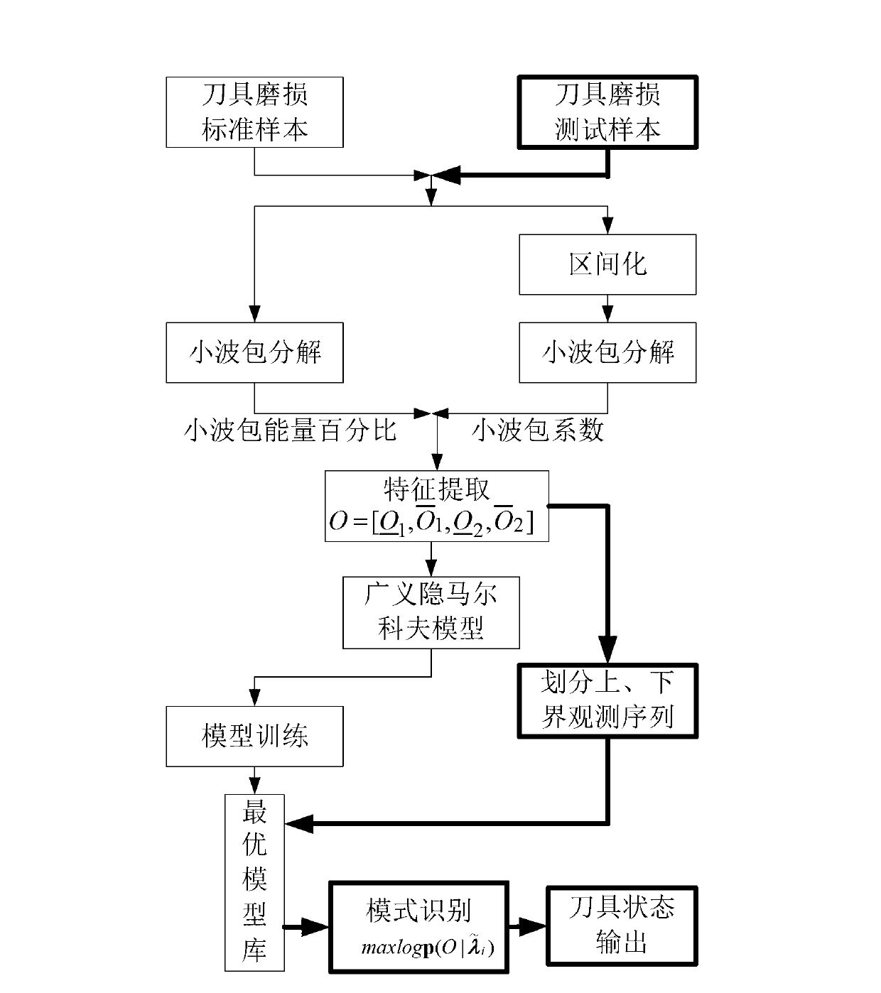
[0034] See attached figure 1 , the tool wear state identification method of the present invention comprises the following steps:

[0035] (1) Data collection

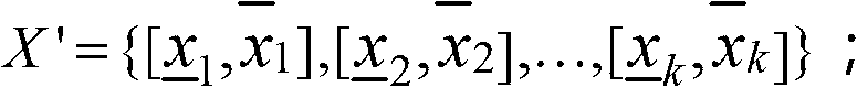
[0036]Tool wear is closely related to cutting force. The measurement tool used in this embodiment is a dynamometer, and the measurement data under various wear states of CNC machine tool cutting are obtained through the dynamometer, which is used as the tool wear force signal data set X={x 1 , x 2 ,...,x k}, where k=1, 2, ..., m, m is the number of measured data, x 1 , x 2 ,...,x k Refers to the multiple measurement values ​​of measurement data, that is, sampling values.

[0037] There are generally four types of tool wear states, namely normal, light wear, severe wear and damage. The measurement data can be one of cutting force, acceleration, acoustic emission, torque, current a...


PUM


Abstract

The invention discloses a machining cutter abrasion state identification method of a numerical control machine tool. The method comprises a first step of data collection, a second step of regionalizing the collection data and obtaining an interval dataset, a third step of conducting wavelet packet decomposition of a collection signal and obtaining an energy percentage of each frequency range and an upper bound wavelet packet coefficient and a lower bound wavelet packet coefficient corresponding to each frequency range, a fourth step of obtaining a multiple observation sequence, a fifth step of obtaining a general hidden Markov original model lambada=(A, B, pi), a sixth step of model training and obtaining an optimal model base lambada=(lambada 1, ..., lambada n), and a seventh step of regarding the to-be-identified cutter abrasion signal data as multiple observation input, substituting into the optimal model base and identifying the cutter abrasion state. The method solves the problem of uncertainty in data processing when the cutter abrasion state is studied in the numerical control machine tool machining through a general interval probability and identifying accuracy rate is greatly improved.

Description

technical field [0001] The invention relates to the field of engineering state identification, in particular to a tool wear state identification method during CNC machine tool cutting. Background technique [0002] In the cutting process of CNC machine tools, the cutting tool is the direct executor of the metal cutting process. Under the condition of high temperature and high pressure, it is subject to the severe friction of the workpiece and chips, and there is inevitably a phenomenon of tool wear, which eventually leads to changes in the state of the tool. The change of tool state will directly lead to the increase of cutting force, the increase of cutting temperature, the increase of workpiece surface roughness, the out-of-tolerance of workpiece size, the change of cutting color and the generation of cutting vibration, and even affect the normal operation of the entire CNC machining system, resulting in unfavorable estimated loss. Therefore, the timely identification and...

Claims


Application Information

Patent Timeline
IPC IPC(8): G05B19/4065
Inventor 谢锋云胡友民吴波贾广飞金超王小岑程瑶
Owner HUAZHONG UNIV OF SCI & TECH
Why Eureka
Try Eureka