
An electronic current transformer and its high-voltage side online energy harvesting device

A technology of current transformers and energy harvesting devices, which is applied in the direction of inductors, voltage/current isolation, transformer/inductor cores, etc., and can solve problems such as high technical difficulty, damage to power supply circuits, and unspecified energy supply power.

Inactive Publication Date: 2016-12-28
HENAN UNIV OF SCI & TECH
View PDF9 Cites 0 Cited by
  • Summary
  • Abstract
  • Description
  • Claims
  • Application Information

AI Technical Summary

Problems solved by technology

[0004] The online energy harvesting circuit of the current transformer coil is simple and low in cost, but the difficulty in its application is that the bus current is not a stable value, and the range of variation is very large. When the bus current is a small current close to no-load, it is difficult for the transformer to obtain enough energy; when When the bus current is in a high current state, the magnetic saturation of the iron core will cause the secondary winding to generate a high-amplitude peak pulse voltage, which needs to be suppressed because it is easy to cause damage to the power circuit. It is technically difficult to obtain higher power, so there is an upper and lower limit current dead zone in this energy supply method, so the magnetic induction coil must take into account the minimum and maximum limit conditions at the same time, and the subsequent processing circuit must have a protection function to ensure stable voltage output. Otherwise, it may cause subsequent circuit burnout
The laser energy supply performance is stable, but the structure is complex, the energy supply power is small, the cost is high, the laser life is short, and the cost of the laser itself is high and the transmission power is strictly limited. If the number of optical fibers is increased, the cost will inevitably increase
The energy supply method of rechargeable batteries has problems such as photoelectric conversion efficiency and battery aging, and its reliability is difficult to guarantee
[0005] Chinese patent CN101309057A discloses an ultrasonic energy supply device. Although the energy supply power is relatively large, the structure is complicated and the working reliability cannot be guaranteed.
[0007] Chinese patent CN201219065Y discloses an active electronic photoelectric current transformer hybrid energy supply device, which uses two online energy-taking current transformers to take into account the minimum and maximum bus current limit conditions, and uses laser energy supply technology to solve the current The problem of dead zone, the structure of this device is relatively complex and the size of the power supply is not specified
[0008] Chinese patent CN202352507U discloses an energy supply device for the high-voltage side of an electronic current transformer. The device adopts a combination of coil energy acquisition and laser energy supply. However, the energy acquisition coil in the device has a large current on the bus It will be difficult to obtain high power energy stably due to saturation

Method used


Image

  • An electronic current transformer and its high-voltage side online energy harvesting device
  • An electronic current transformer and its high-voltage side online energy harvesting device

Examples


Embodiment Construction

[0025] The present invention will be further described below in conjunction with the accompanying drawings and specific embodiments.

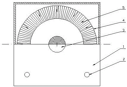
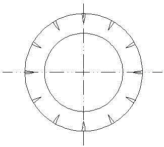
[0026] like figure 1 Shown is a schematic structural diagram of the high-voltage side online energy harvesting device of the electronic current transformer of the present invention. It can be seen from the figure that the high-voltage side online energy harvesting device of the current transformer includes a shielding shell 1, and the shielding shell is built with an iron core 4 and a secondary Winding 5, the secondary winding is wound on the iron core, the lead-out terminal of the secondary winding is connected to the terminal 2 of the shielding shell, the iron core adopts an annular laminated iron core, and a group of magnetic valves are arranged on the outer circumference of the iron core , The magnetic valve is provided with a radially extending narrow slot, the narrow slot axially penetrates the front end face and the rear end face of the ...


PUM


Abstract

The invention discloses an electronic current transformer and a high-voltage side on-line energy-receiving device of the electronic current transformer. The electronic current transformer and the on-line energy-receiving device of the high-voltage side of the electronic current transformer comprises a high-voltage side electricity-using unit and a high-voltage side energy-receiving device for supplying electricity to the high-voltage side energy-receiving device. The high-voltage side on-line energy-receiving device comprises a shielding shell, wherein an iron core and a secondary winding are internally arranged in the shielding shell, the secondary winding is winded on the iron core, a leading-out terminal of the secondary winding is connected on a connecting terminal externally arranged on the shielding shell, an annular laminated core is adopted as the iron core, a group of magnetic valves is arranged on the periphery of the iron core, and a narrow groove is arranged on the magnetic valves and extends along the radial direction, and penetrates through the front end surface and the rear end surface of the iron core along the radial direction. Because the group of magnetic valves is arranged on the iron core, not only the problem that when the current of a bus is large, a traditional current transformer can not stably obtain energy with large power because of saturation is solved, but also upper limit of a current dead zone can be increased to more than 20000A.

Description

technical field [0001] The invention belongs to the technical field of electric power systems, and in particular relates to an electronic current transformer and an online energy harvesting device on the high-voltage side thereof. Background technique [0002] In modern power systems, electronic transformers are key equipment for monitoring the operating status of primary equipment and systems. Among them, the electronic current transformer is divided into active type and passive type according to whether the high-voltage side needs power supply. With the promotion of microelectronics technology and optical fiber technology, active electronic transformers with relatively mature technology, reasonable cost and good stability have been paid attention to. Active electronic current transformers have excellent insulation performance and no magnetic saturation. Excellent characteristics, adapt to the needs of large capacity, high voltage level and automation development of power ...

Claims


Application Information

Patent Timeline
Patent Type & Authority Patents(China)
IPC IPC(8): H01F38/30H01F27/40H01F27/24G01R15/18
Inventor 王程远尚振东高春艳李春梅黄晓东苏建新贾天义徐凯
Owner HENAN UNIV OF SCI & TECH
Learn More