Balance type radio frequency electronically-controlled band-pass filter with bandwidth control

A band-pass filter and bandwidth control technology, applied in waveguide devices, circuits, resonators, etc., can solve problems that have not yet been described, and achieve the effect of widening the stop band

Inactive Publication Date: 2013-05-15
NANJING UNIV OF SCI & TECH
View PDF4 Cites 25 Cited by
  • Summary
  • Abstract
  • Description
  • Claims
  • Application Information

AI Technical Summary

Problems solved by technology

[0006] (3) stopband extension
[0010] In short, the current technology still needs to solve the problem of controlling the bandwidth wh

Method used


Image

  • Balance type radio frequency electronically-controlled band-pass filter with bandwidth control
  • Balance type radio frequency electronically-controlled band-pass filter with bandwidth control
  • Balance type radio frequency electronically-controlled band-pass filter with bandwidth control

Examples


Embodiment 1

[0053] Implementation example 1: Realize a balanced RF electronically tunable filter with a constant absolute bandwidth of 95MHz

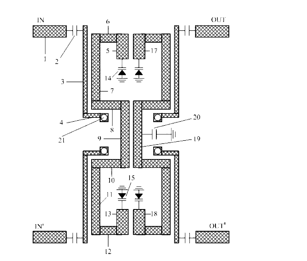
[0054] The structure of the balanced RF electronically tuned filter with a constant absolute bandwidth of 95MHz at an operating frequency of 733MHz-1603MHz is as follows: figure 1 shown. The specific parameters are: the first rectangular microstrip line 5 is 4.3mm long and 1.2mm wide; the second rectangular microstrip line 6 is 3mm long and 1mm wide; the third rectangular microstrip line 7 is 11mm long and 1mm wide; the fifth rectangular microstrip line The line 9 is 8mm long and 1mm wide; the distance between the center of the ground via 21 connected to the eleventh rectangular microstrip line 4 and the fifth rectangular microstrip line 9 is 0.8mm; the capacitance value of all DC blocking capacitors is 10pF; The capacitance value of the capacitor 20 loaded in the middle of the second half-wavelength step impedance resonator is 10pF; the first rec...

Embodiment 2

[0055] Implementation example 2: Realize a balanced RF electronically tunable filter with a constant relative bandwidth of 9.8%

[0056] 726MHz—1625MHz The structure of a balanced RF electronically tuned filter with a constant relative bandwidth of 9.8% is as follows: figure 1 shown. The specific parameters are: the first rectangular microstrip line 5 is 4.3mm long and 1.3mm wide; the second rectangular microstrip line 6 is 3mm long and 1mm wide; the third rectangular microstrip line 7 is 11mm long and 1mm wide; the fifth rectangular microstrip line The line 9 is 8mm long and 1mm wide; the distance between the center of the ground via 21 connected to the eleventh rectangular microstrip line 4 and the fifth rectangular microstrip line 9 is 0.8mm; the capacitance value of all DC blocking capacitors is 10pF; The capacitance value of the capacitor 20 loaded in the middle of the second half-wavelength step impedance resonator is 10pF; the first rectangular microstrip line 5 (the f...


PUM

PropertyMeasurementUnit
Heightaaaaaaaaaa

Abstract

The invention relates to a balance type radio frequency electronically-controlled band-pass filter with bandwidth control. The balance type radio frequency electronically-controlled band-pass filter with bandwidth control is composed of an upper layer micro-strip structure, an intermediate layer dielectric substrate and a lower layer grounded metal. Two input ports in the upper layer micro-strip structure are respectively connected with two input feed networks, and two output ports are respectively connected with two output feed networks. Two input feed networks are coupled with a first half-wavelength phrase step impedance resonator, a first half-wavelength phrase step impedance resonator is coupled with a second half-wavelength phrase step impedance resonator, finally the second half-wavelength phrase step impedance resonator is coupled with two output feed networks, and the whole filter structure is in a structure of longitudinal mirror symmetry. The balance type radio frequency electronically-controlled band-pass filter with bandwidth control achieves flexible bandwidth control, has the advantages of being high in common-mode rejection ration and wide in stop band and can be used for a reconfigurable radio frequency front end of the wireless communication or a radar system.

Description

technical field [0001] The present invention relates to a new type of balanced radio frequency electrical tuning bandpass filter based on varactor diodes, especially a balanced radio frequency with bandwidth control that can be applied in multi-band, broadband and reconfigurable radio frequency front-end systems ESC bandpass filter. Background technique [0002] ESC filter is one of the key technologies in hopping spread spectrum communication technology, anti-jamming radar, dynamic frequency allocation technology, multi-function receiver, spurious emission measurement, etc. Since World War II, electronically tunable filters have always been one of the research hotspots in various countries. In this regard, there have been some research reports, and a variety of different tuning devices have also been used, such as semiconductor varactors, radio frequency micro-electromechanical systems (RF MEMS) capacitors, and ferroelectric thin-film material varactors. Among them, semic...

Claims


Application Information

Patent Timeline
IPC IPC(8): H01P1/203H01P7/08
Inventor 车文荃毛金荣冯文杰王晴马亚林李飞周家根
Owner NANJING UNIV OF SCI & TECH
Why Eureka
Try Eureka