
Multi-focal laser processing system

A laser processing and multi-focus technology, applied in the laser field, can solve problems such as damage, transverse cracks on the workpiece, and reduce the efficiency of laser equipment, so as to achieve the effects of improving product quality, increasing processing speed, and wide application

Inactive Publication Date: 2013-05-22
WUHAN DR LASER TECH CORP LTD
View PDF6 Cites 8 Cited by
  • Summary
  • Abstract
  • Description
  • Claims
  • Application Information

AI Technical Summary

Problems solved by technology

[0005] These lenses are all for concentrating the laser beam on a single focal point with the smallest diameter. In actual laser cutting, especially in the cutting of materials with high absorptivity such as LED wafers, the defects formed by a single focal point are limited. LED wafers with a thickness of less than 150 microns can be cut for defects. When cutting LED wafers larger than 150 microns, the usual method is to cut the same position twice or more times. The difference between each cut is Let the focal point change along the optical axis direction to achieve the goal, which greatly reduces the efficiency of the laser equipment
In practical applications, because the laser focus spot size is between a few microns and tens of microns, the mechanical precision of the equipment is difficult to ensure that each defect is located at the same cross-sectional position of the material during multiple cuttings, usually in the later splitting process , can cause transverse cracks or even damage the entire workpiece
This makes it difficult to guarantee the yield rate and good cutting process quality, resulting in the formation of waste or defective products

Method used


Image

  • Multi-focal laser processing system

Examples


Embodiment Construction

[0018] The technical solutions of the present invention will be described in detail below in conjunction with the accompanying drawings and specific embodiments. The schematic embodiments and descriptions of the present invention are used to explain the technical solutions of the present invention, but are not intended to limit the present invention.

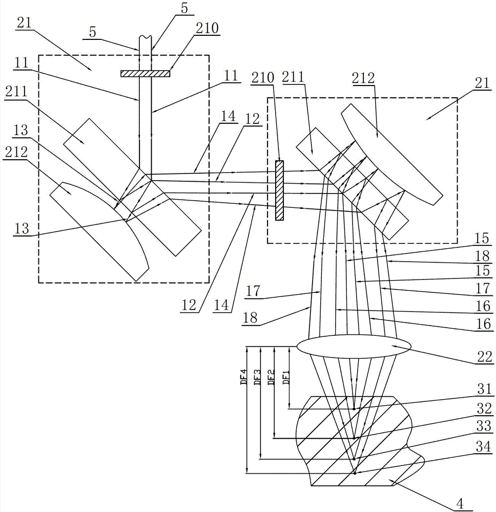
[0019] The four-focus laser processing system in the present invention includes two optical element combinations 21 and a focusing mirror 22 serially connected in series on the optical path. The optical element combination 21 includes a wave plate 210 , a beam splitter 211 and a convex mirror 212 .

[0020] The detailed optical path diagram of the four-focus laser processing system in the present invention is as follows figure 1 Shown:

[0021] The first part: the incident light beam 5 passes through the optical element combination 21:

[0022] The incident light beam 5 passes through the wave plate 210 to obtain the first ligh...


PUM

PropertyMeasurementUnit
Focal lengthaaaaaaaaaa

Abstract

The invention provides a multi-focal laser processing system which comprises two or more than two optical element assemblies and a focus lens, wherein the optical element assemblies are sequentially connected with an optical path in series, an incident beam passes through two or more than two optical element assemblies which are sequentially connected with the optical path in series, is focused by the focus lens, and then acts on the focal point of an optical axis of a work piece to be processed. Each optical element assembly comprises a spectroscope and a convex mirror. The incident beam is reflected through the spectroscope to obtain a first incident beam which enters the next optical element assembly. The incident beam is transmitted through the spectroscope and a light beam is obtained, and the light beam is reflected through the convex mirror and transmitted through the spectroscope to obtain a second incident beam which enters the next optical element assembly. Through the adoption of the technical scheme of the multi-focal laser processing system, the incident beam forms a plurality of focuses through the multi-focal laser processing system, the number of the focuses is a multiple of 4, and therefore processing speed and quality of products are improved.

Description

technical field [0001] The invention relates to the field of lasers, and discloses a multi-focus laser processing system for transparent materials such as LED wafers, ceramics, silicon chips, and glass. Background technique [0002] Laser cutting technology has now become a mature industrial processing technology. In addition to the traditional metal as the main object of cutting, cutting technology such as LED wafers, ceramics, silicon wafers and glass as cutting objects has become an emerging research direction. [0003] In the process of research, we found that the laser cutting technology of transparent materials such as LED wafers as the cutting object is different in principle from the laser cutting of traditional technology. Their laser cutting is a pre-cutting method. Formed by crystallization, the end-point pulse energy of the laser focus will disrupt the structure between the grains and form defects between the grains. Laser cutting itself does not separate the cut...

Claims


Application Information

Patent Timeline
IPC IPC(8): B23K26/067B23K26/06B23K26/064
Inventor 李志刚
Owner WUHAN DR LASER TECH CORP LTD
Learn More