Planning method of motion path of wafer cutting machine tool

A technology for cutting machine tools and motion paths, applied in welding equipment, laser welding equipment, metal processing equipment, etc., can solve the problems of wasting deceleration and restarting time, low work efficiency, etc., saving time, improving efficiency, and reducing waste. effect of time

Active Publication Date: 2013-05-22
福建省威诺数控有限公司
View PDF7 Cites 13 Cited by
  • Summary
  • Abstract
  • Description
  • Claims
  • Application Information

AI Technical Summary

Problems solved by technology

This decelerates the Y-axis motor motion platform to zero, and then moves the X-axis motor motion platform to the corresponding position, then the Y-axis motor motion platform starts to accelerate to the set s

Method used


Image

  • Planning method of motion path of wafer cutting machine tool
  • Planning method of motion path of wafer cutting machine tool
  • Planning method of motion path of wafer cutting machine tool

Examples


Embodiment Construction

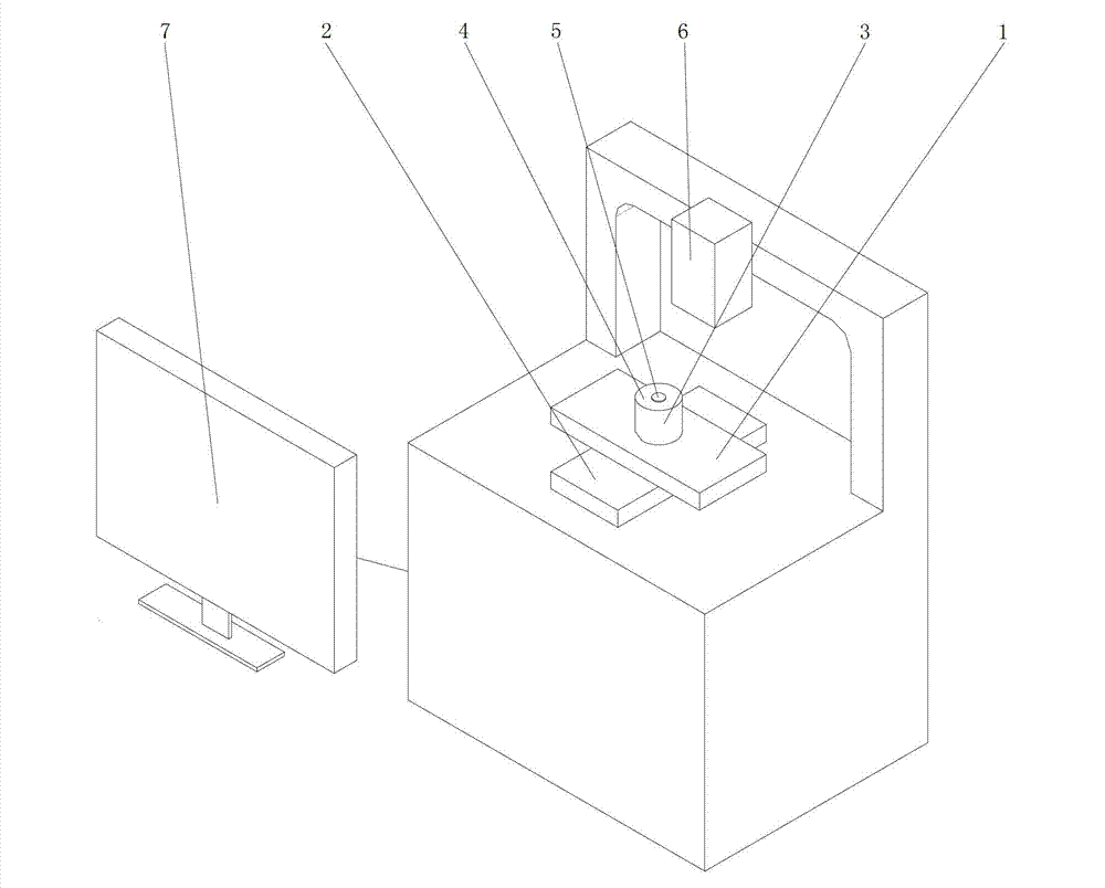
[0031] Such as Figure 3-7 As shown, a method for planning the movement path of a wafer cutting machine tool in the present invention, the wafer cutting machine tool used in the planning method includes X, Y axis motor motion platforms 1, 2, X, Y axis motor motion platforms 1, 2 A rotating motor platform 3 is provided, and a worktable 4 is arranged on the rotating motor platform 3. The wafer 5 is fixed on the workbench 4. A fixed laser 6 is arranged above the workbench 4. The laser beam emitted by the laser 6 is The wafer 5 on the quasi-workbench, the wafer cutting machine tool also includes a controller 7 with a CPU, the controller 7 is electrically connected to the X and Y axis motor movement platforms 1, 2, and the rotating motor platform 3 respectively, and the controller 7. Wafer processing parameters are pre-stored in it;

[0032] The planning method of the present invention comprises the following steps:

[0033] 1) When the wafer 5 is cut, input the processing parame...


PUM


Abstract

The invention discloses a planning method of a motion path of a wafer cutting machine tool. The method comprises the following steps: (1) a wafer is driven by a Y shaft motor moving platform to conduct line cutting motion along the vertical direction; (2) when the wafer reaches the end portion of the cutting line of the wafer along the vertical direction, a circular interpolation module is started, an X shaft motor moving platform is in linkage with the Y shaft motor moving platform so as to drive the wafer to conduct circular motion; (3) circular interpolation is finished, the wafer reaches the end portion of the cutting line along the adjacent vertical direction so as to conduct cutting to another cutting line of the vertical direction; (4) the above steps are repeated so as to finish all line cutting of the vertical direction; and (5) all cutting of transverse cutting lines is conducted by utilizing similar operation. According to the planning method of the motion path of the wafer cutting machine tool, the cutting path of the wafer is planned reasonably, time waste caused by excessive miscut when laser beams are at two ends of the wafer is reduced; meanwhile, the X shaft motor moving platform and the Y shaft motor moving platform operate simultaneously in the circular motion of a miscut area, a large amount of time is saved, and working efficiency is improved.

Description

technical field [0001] The invention relates to a wafer cutting machine tool in a numerically controlled machine tool, in particular to a planning method for a motion path of a wafer cutting machine tool. Background technique [0002] With the advent of the information age, industries such as electronic information, communications, and semiconductor integrated circuits have developed rapidly, semiconductor wafers have been widely used, and the demand is increasing. Wafer cutting and dicing is not only one of the core key processes of chip packaging, but also a landmark process for the transition from wafer-level processing to chip-level processing. Wafer preparation technology and process have higher and higher requirements for yield rate and work efficiency in mass production of wafer cutting and scribing. [0003] Therefore, at present, the demand for wafer cutting equipment at home and abroad is increasing, and the requirements are getting higher and higher, especially i...

Claims


Application Information

Patent Timeline
IPC IPC(8): B23K26/38
Inventor 翁强
Owner 福建省威诺数控有限公司
Why Eureka
Try Eureka