Spring-type quenching clamp assembly

A technology of assembly, limit fixture, applied in the direction of manufacturing tools, furnace types, furnaces, etc.

Active Publication Date: 2013-05-22
亚捷(无锡)热工科技有限公司
View PDF7 Cites 2 Cited by
  • Summary
  • Abstract
  • Description
  • Claims
  • Application Information

AI Technical Summary

Problems solved by technology

[0003]The product has large deformation after quenching
Due to the combined effect of thermal stress and structural transformation stress, thin-walled parts deform greatly; free quenching or other simple forms of limited quenching are difficult to ensure that the predetermined deformation range is reached after quenching, which increases the difficulty of subsequent processing and production improvement.
[0004]The production efficiency is low. Due to the limitation of the equipment, it can only be operated automatically with a single station or a double station, or manual operation. The number of stations is small and the production efficiency is low.
[0005]Due to large deformation, material utilization rate is low and often results in scrap

Method used


Image

  • Spring-type quenching clamp assembly
  • Spring-type quenching clamp assembly
  • Spring-type quenching clamp assembly

Examples


Embodiment Construction

[0026] The present invention is described in detail below in conjunction with accompanying drawing and embodiment:

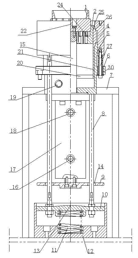
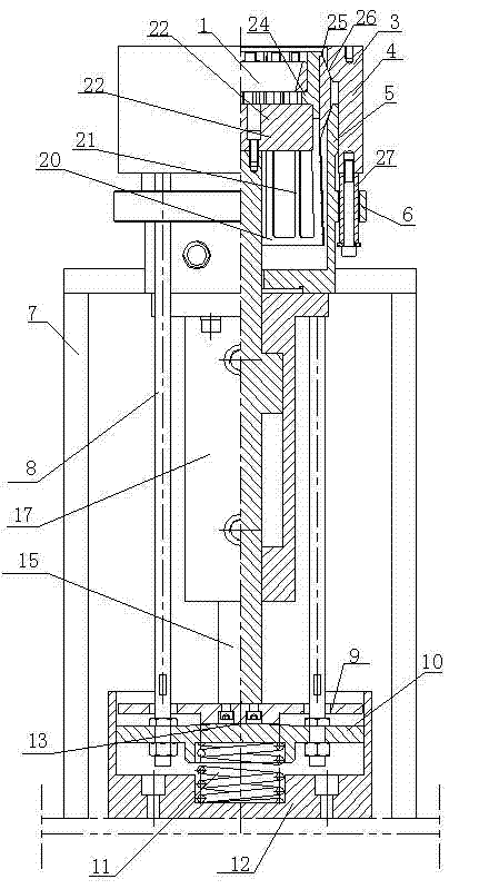
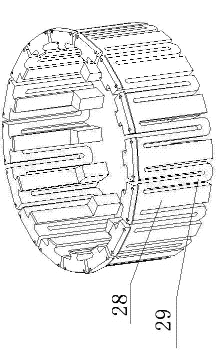
[0027] A spring type quenching fixture assembly, see attached figure 1 To attach Figure 5 , in the figure: workpiece 1, limit fixture 2, clamping body 3, outer sleeve 4, inner sleeve 5, shoulder structure 6, bracket 7, connecting rod 8, pressure plate 9, pressure sleeve 10, compression spring 11, bottom sleeve 12 , Protruding structure 13, Through hole 14, Piston rod 15, Second oil hole 16, Oil cylinder housing 17, First oil hole 18, Quenching oil hole 19, Ring chassis 20, Branch structure 21, Bracket 22, Boss 24 ; annular flange 25 ; slope structure 26 , guide column 27 , bar 28 , U-shaped structure 29 , guide hole 30 , and extension plate 31 .

[0028] In this example, see the attached figure 1 to attach Figure 5 The clamping body 3 is composed of the lower annular chassis 20 and the upper branch structure 21; the inner sleeve 5 is placed under...


PUM


Abstract

The invention relates to a clamp assembly which is used for quenching a workpiece and in particular relates to a spring-type quenching clamp assembly. The spring-type quenching clamp assembly comprises a rack, an outer sleeve, an inner sleeve, a limiting clamp and a clamping body, wherein the inner sleeve is arranged below the outer sleeve; a quenching oil hole is formed on the inner sleeve; the extending end of the inner sleeve is arranged on the inner part of the outer sleeve; an inclined surface structure which is fitted with the outer sleeve and the inner sleeve is arranged on a branch structure, respectively; an annular flange for supporting the limiting clamp is supported at the top end of the branch structure; a boss is arranged in the limiting clamp; the limiting clamp is supported by a bracket and arranged on the inner part of the inner sleeve; and the bracket is connected with a drive device. Compared with the prior art, the spring-type quenching clamp assembly has the advantages of reducing the deflection after quenching, reducing the subsequent processing amount and the processing amount of the early process, and reducing the cost; the spring-type quenching clamp assembly can be fitted to various associated equipment and can be used for realizing various working modes such as a continuous working mode, a single-step working mode, and the like; moreover, the optional range is large and the production efficiency is greatly improved; the limited-type quenching of the workpieces with different sizes can be realized by changing the clamping body; and the mould is simple and convenient to change.

Description

technical field [0001] The invention relates to a fixture assembly for quenching workpieces, in particular to a spring type quenching fixture assembly. Background technique [0002] At present, when quenching workpieces of rotating bodies such as bearing rings and friction rings, free quenching or other simple forms of limited quenching are used. There are following limitations and deficiencies: [0003] The product is deformed after quenching. Due to the combined effect of thermal stress and structural transformation stress, thin-walled parts deform greatly; free quenching or other simple forms of limited quenching are difficult to ensure that the predetermined deformation range is reached after quenching, which increases the difficulty of subsequent processing and production improvement. . [0004] The production efficiency is low. Due to the limitation of the equipment, it can only be operated automatically with a single station or a double station, or manual operation...

Claims


Application Information

Patent Timeline
Patent Type & Authority Applications(China)
IPC IPC(8): C21D9/02
Inventor 郝宗合涂德桓刘怀英
Owner 亚捷(无锡)热工科技有限公司
Why Eureka
Try Eureka