Supersonic missile anti-drag wings

A supersonic and missile technology, applied in the field of modern aerospace, can solve problems such as sudden increase in resistance and congestion

Inactive Publication Date: 2013-05-22
NORTHWESTERN POLYTECHNICAL UNIV
View PDF4 Cites 7 Cited by
  • Summary
  • Abstract
  • Description
  • Claims
  • Application Information

AI Technical Summary

Problems solved by technology

However, this Busemann wing will appear "choked up" when it deviates from the design Mach number, and the resistance will increase sharply even much greater than the conventional wing layout (such as diamond wing)
Since there is no good solution to the sharp increase in drag caused by the choked flow that occurs when deviating from the design point, Busemann's biplane theory has not been specifically applied to actual supersonic aircraft for half a century

Method used


Image

  • Supersonic missile anti-drag wings
  • Supersonic missile anti-drag wings
  • Supersonic missile anti-drag wings

Examples


Embodiment Construction

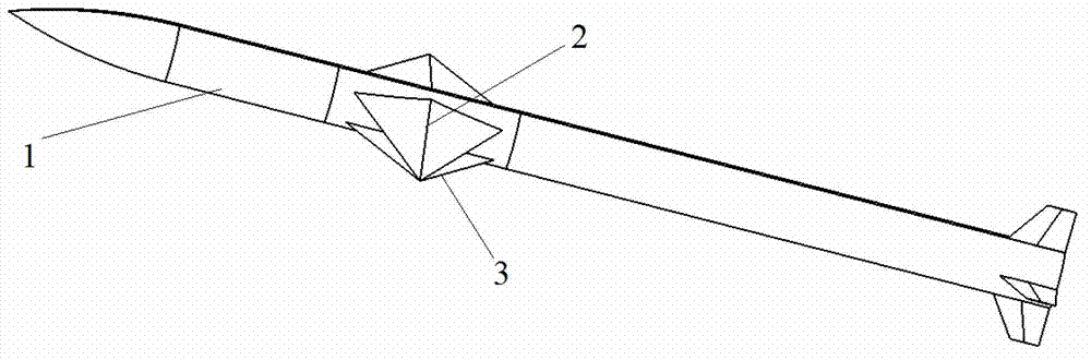
[0031] This embodiment is a drag reduction wing of a supersonic missile, which includes two sets of wings and four driving mechanisms.

[0032] In this embodiment, the incoming direction of the projectile 1 is the projectile.

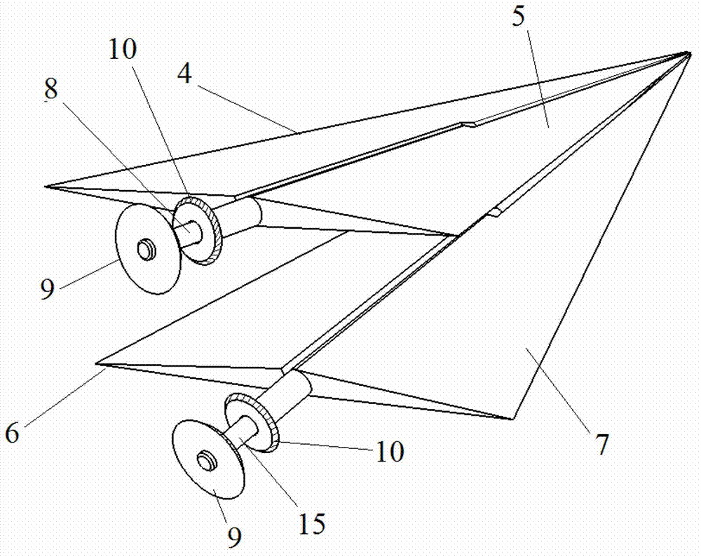
[0033] Two sets of projectile wings are symmetrically distributed on both sides of projectile body 1, and are located at 38% of the projectile axis length from the direction of the warhead. Each set of elastic wings includes an upper wing 2 , a lower wing 3 , a central axis 8 of the upper wing and a central axis 15 of the lower wing.

[0034] The four driving mechanisms are divided into two groups, wherein each group of driving mechanisms includes a driving mechanism for the upper blade 2 and a driving mechanism for the lower blade 3 . The two sets of driving mechanisms are located at the 0% spanwise end of the elastic wing, wherein the central axis gear 9 and the bushing gear 10 of the two sets of driving mechanisms are respectively sleeved on the cen...


PUM


Abstract

Disclosed are supersonic missile anti-drag wings. Two sets of missile wings are distributed on two sides of a missile body symmetrically. Each missile wing comprises an upper wing piece and a lower wing piece. Root chord lengths of the upper wing pieces and the lower wing pieces are both 0.52m, and stretching lengths of the upper wing pieces and the lower wing pieces are both 0.52m. The upper reflex angle of each upper wing piece is -9 degrees, and the upper reflex angle of each lower wing piece is 9 degrees. The leading edge backward sweep angles of the upper wing pieces and the lower wing pieces are both 63.6 degrees. Each upper wing piece and each lower wing piece are respectively connected with a driving mechanism. When a Mach number of a supersonic cruise missile is lower than a design point, the upper wing pieces on the two sides of the missile body deflect downwards, the lower wing pieces deflect upwards so that the area ratio of the maximum thickness portion of the wings and the leading edge inlet is 1. Upper stream passes between the wings so that occurrence of jamming is avoided. When the Mach number continues to increase and reaches the designed Mach number, the upper wing pieces on the two sides of the missile body deflect upwards, the lower wing pieces deflect downwards, and the Busemann double-wing outward position is realized. Shock wave resistance can be reduced by utilizing wave interference effect of shock wave weakening and shock wave expanding.

Description

technical field [0001] The invention relates to the field of modern aerospace, in particular to a variable bi-wing drag reduction configuration of a supersonic missile. Background technique [0002] For supersonic cruise missiles, wave resistance is an important part of the total resistance, and cruise missiles will fly at the designed Mach number in the cruise state most of the time. horn. In order to improve the aerodynamic performance of the missile in the cruise state, thereby increasing its range, it is very important to reduce the wave resistance in the cruise flight state. As the main load-bearing component of cruise missiles, the resistance generated by the wing, especially the shock wave resistance, accounts for a large part of the total resistance. It is very difficult to reduce the wave resistance by significantly weakening the shock wave intensity on it by conventional layout. [0003] As early as 1935, Adolf Busemann proposed to place a wing in parallel on the...

Claims


Application Information

Patent Timeline
Patent Type & Authority Applications(China)
IPC IPC(8): F42B10/38
Inventor 叶正寅华如豪李伟杰田八林张伟伟武洁
Owner NORTHWESTERN POLYTECHNICAL UNIV
Why Eureka
Try Eureka