Three-level hysteresis current tracking inverter and control method of three-level hysteresis current tracking inverter

A three-level inverter and hysteresis current technology, which is applied in the direction of converting AC power input to DC power output, electrical components, output power conversion devices, etc., can solve the problem of increased electromagnetic interference, inaccurate judgment, and difficulty in obtaining sufficient play and other issues

Active Publication Date: 2014-12-10
SHANDONG HOTEAM ELECTRICAL
View PDF6 Cites 0 Cited by
  • Summary
  • Abstract
  • Description
  • Claims
  • Application Information

AI Technical Summary

Problems solved by technology

The output of the three-level inverter bridge has three states: positive level, zero level and negative level, and the conventional two-state hysteresis tracking control method cannot be applied
Several three-state hysteresis tracking control methods have been proposed in relevant research literature, one of which is to use the polarity of the output voltage as an additional judgment condition to construct a three-state output drive signal. Due to defects in the principle, it cannot be accurately judged to achieve correct tracking. In the second type of three-state hysteresis loop current tracking control method, in addition to the upper and lower limits of the hysteresis loop tracking error band, it is also necessary to add a new comparison level in the error band, and add three The switching times of semiconductor power devices in the level inverter bridge will lead to increased switching stress and loss of power devices, and increased electromagnetic interference; the third type of three-state hysteresis current tracking control method is to introduce a sequential circuit controlled by clock pulses, and The hysteresis comparator is combined to complete the three-state control, and there is a problem of tracking lag and real-time deterioration
The hysteresis current tracking control method of the known three-level inverter, due to various defects, makes it difficult to fully utilize the advantages of the hysteresis tracking control method in the three-level inverter

Method used


Image

  • Three-level hysteresis current tracking inverter and control method of three-level hysteresis current tracking inverter
  • Three-level hysteresis current tracking inverter and control method of three-level hysteresis current tracking inverter
  • Three-level hysteresis current tracking inverter and control method of three-level hysteresis current tracking inverter

Examples


Embodiment 1

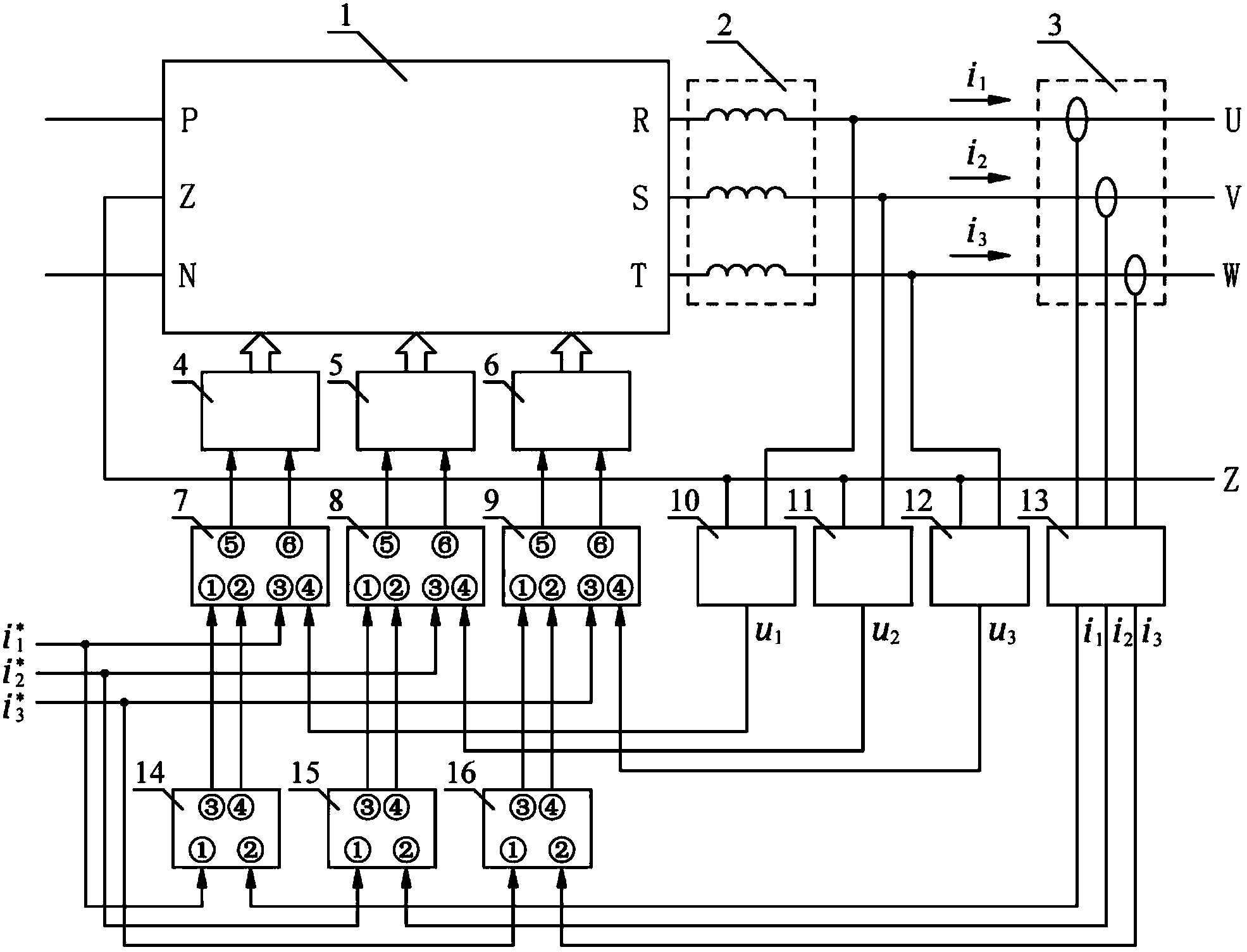
[0082] A three-level hysteretic current tracking inverter, such as figure 1 As shown, it includes a three-level inverter bridge 1, an inductor 2, a current sensor group 3, a first drive unit 4, a second drive unit 5, a third drive unit 6, a first drive control unit 7, a second drive unit Control unit 8, third drive control unit 9, first voltage detection unit 10, second voltage detection unit 11, third voltage detection unit 12, current detection unit 13, first hysteresis comparison unit 14, second hysteresis comparison unit Unit 15, the third hysteresis comparison unit 16, wherein:

[0083] The output terminals R, S and T of the three-level inverter bridge 1 are respectively connected to the three input terminals of the inductor 2, and the three output terminals of the inductor 2 are respectively connected to the three terminals of the three-level hysteresis current tracking inverter. Phase output U, V, W;

[0084] The two input terminals of the first voltage detection unit...

Embodiment 2

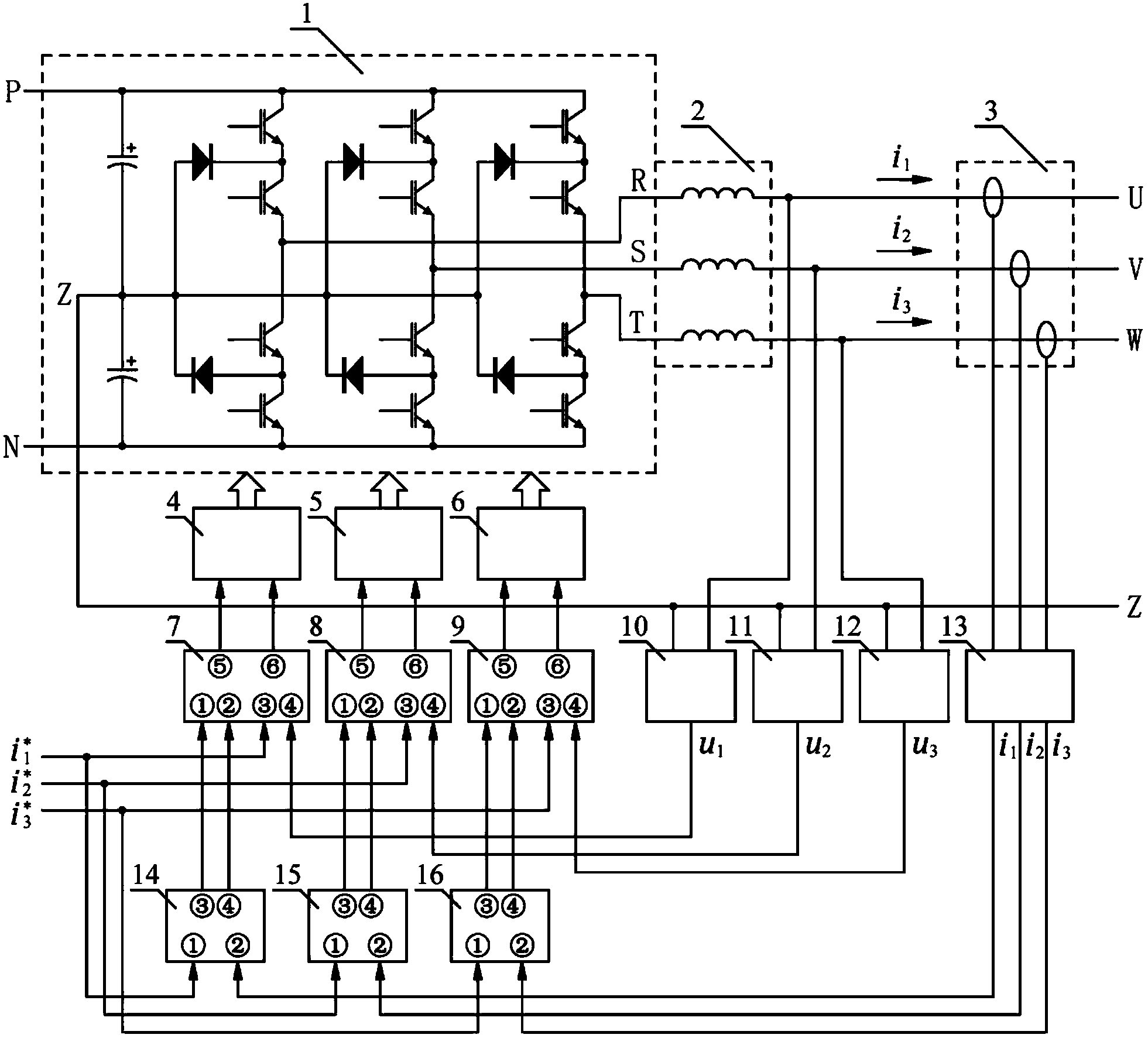
[0145] Such as figure 2 As shown, in this embodiment, the three-level inverter bridge 1 adopts the known diode-clamped three-level inverter bridge. At this time, the zero-level support point Z of the three-level inverter bridge is two The center connection point of the DC bus capacitors. Others are all the same as in Example 1.

Embodiment 3

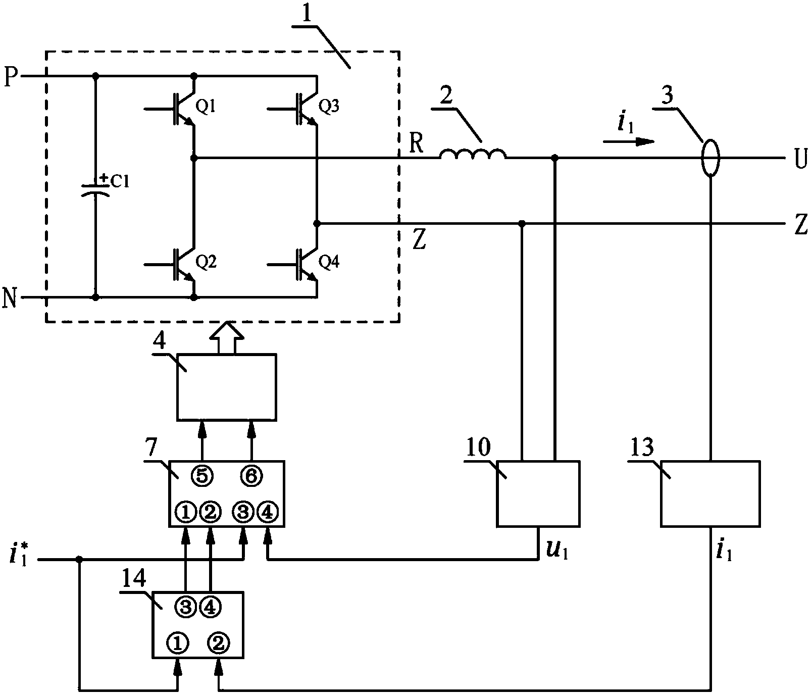
[0147] Such as image 3As shown, this embodiment is an application mode of the device and control method of the present invention in a single-phase inverter. In this embodiment, the three-level inverter bridge 1 adopts a well-known H-type single-phase inverter bridge. At this time, the zero-level support point Z of the three-level inverter bridge is an output terminal of the inverter bridge. Since only single-phase inversion is required, the second drive unit 5, the third drive unit 6, the second drive control unit 8, the third drive control unit 9, the second voltage detection unit 11, and the third voltage detection unit in the device 12. Both the second hysteresis comparison unit 15 and the third hysteresis comparison unit 16 can be deleted, the inductor 2 can be a single-phase inductor, only one current transformer is needed in the current sensor group 3, and the current detection unit 13 only needs to detect one For the phase current, only the variable corresponding to j...


PUM


Abstract

The invention discloses a three-level hysteresis current tracking inverter and a control method of the three-level hysteresis current tracking inverter. An three-level inverter bridge output end is connected with an inductor in series mode and then serves as an output end of the three-level hysteresis current tracking inverter, each voltage detecting unit respectively detects voltage between a zero level supporting point of a three-level inverter bridge and a three-level output end of the inverter, detected results are respectively fed to each driving control unit, a current detecting unit detects three-level output current of the inverter, detected results are respectively fed to each hysteresis comparison unit, three-level command current signals are respectively fed to each hysteresis comparison unit and each driving control unit, output ends of each hysteresis comparison unit are connected with corresponding driving control units, output ends of each driving control unit are connected with corresponding units, and output ends of each driving unit are connected with driving signal input ends of the three-level inverter bridge. The device and the control method can perform hysteresis tracking control on output current of the three-level inverters and have the advantages of being high in tracking accuracy, fast in speed, good in real-time and the like.

Description

technical field [0001] The invention belongs to the technical field of grid-connected inverters, and in particular relates to a three-level hysteresis loop current tracking inverter and a control method thereof. Background technique [0002] The inverter output current control methods include linear PWM control, single-cycle control, hysteresis current tracking control, etc. Among them, the hysteresis current tracking control method has the advantages of fast current tracking speed, good robustness, and simple structure. It is often used in occasions that require high current tracking speed. However, the hysteresis current tracking control method is usually only applicable to two-level inverters. With the development of power electronics technology and the emergence of three-level IGBT power modules, three-level inverters have been increasingly widely valued and applied. Compared with the two-level inverter, the three-level inverter has the advantages of small output rippl...

Claims


Application Information

Patent Timeline
Patent Type & Authority Patents(China)
IPC IPC(8): H02M7/483H02M7/487H02M7/5387
Inventor 李建明迟恩先王德涛鞠洪兵
Owner SHANDONG HOTEAM ELECTRICAL
Why Eureka
Try Eureka