
High-power light emitting diode (LED) lamp heat dissipating device

A technology of LED lamps and heat sinks, which is applied to lighting devices, cooling/heating devices of lighting devices, components of lighting devices, etc., which can solve the problems of large space occupation, poor reliability, and heat accumulation effect of light sources Convenience and ease of replacement

Inactive Publication Date: 2013-05-29
CHONGQING SILIAN OPTOELECTRONICS SCI & TECH
View PDF3 Cites 1 Cited by
  • Summary
  • Abstract
  • Description
  • Claims
  • Application Information

AI Technical Summary

Problems solved by technology

However, due to the high power, high-power LED lamps usually need to add heat dissipation devices. The existing heat dissipation devices are mainly divided into the following two types: 1. Passive heat dissipation, that is, heat dissipation is achieved by setting heat sinks on the LED lamps, but due to This heat dissipation method has no air-permeable structure, and it is easy to accumulate dust and oil, and can only dissipate heat from the LED light through heat conduction and heat radiation. In this way, a large amount of heat energy generated by the LED light source cannot be channeled and dissipated in time through the heat exchange between the heat sink and the air. Excluded, it is easy to lead to the heat accumulation effect of the light source, causing the LED junction temperature to rise, accelerating the LED light decay, affecting the working efficiency and reliability of the LED, and ultimately reducing the life of the LED lamp; 2. Active heat dissipation, that is, through the LED lamp Install a cooling fan to improve cooling efficiency. Although this cooling method has a better cooling effect, it has the disadvantages of taking up a large space, the cooling fan is easily damaged, and the reliability is poor.

Method used


Image

  • High-power light emitting diode (LED) lamp heat dissipating device
  • High-power light emitting diode (LED) lamp heat dissipating device
  • High-power light emitting diode (LED) lamp heat dissipating device

Examples


Embodiment Construction

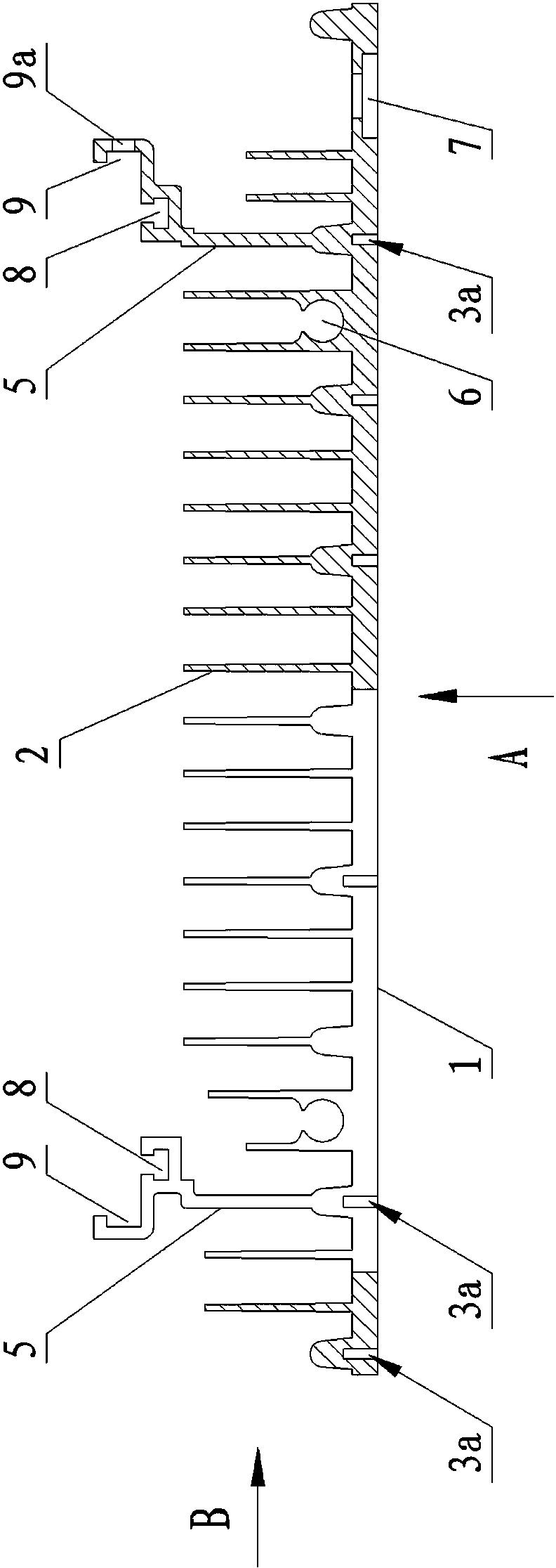
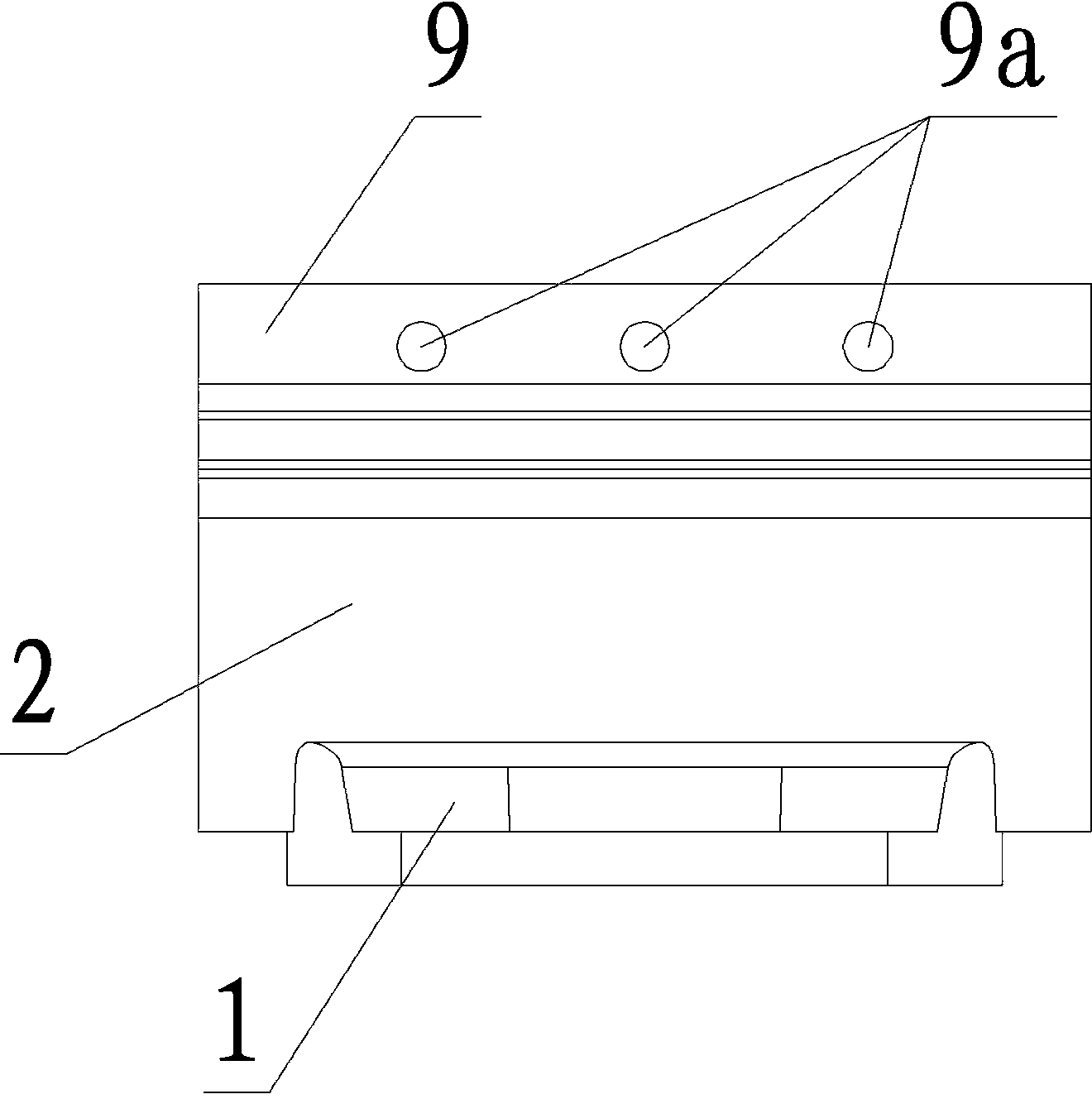
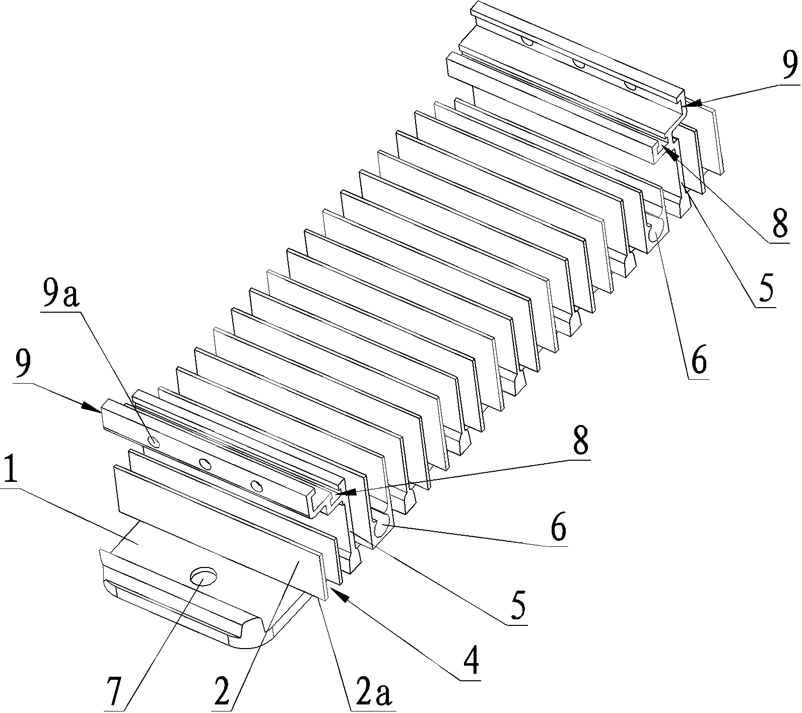
[0019] see Figure 1 to Figure 4 , a heat dissipation device for high-power LED lamps, comprising a base plate 1 with a plurality of heat sinks 2 on one side, the heat sinks 2 are perpendicular to the base plate 1, and the distance between two adjacent heat sinks is > 10mm, which can not only improve heat dissipation efficiency, but also It also prevents the accumulation of dust and oil. One side of the substrate 1 is an installation surface 3 for installing LED lamps. The installation surface 3 is provided with several installation screw holes 3a, and the several installation screw holes 3a include a lamp board fixing hole 3a1 arranged along the transverse centerline of the installation surface 3 and the lampshade fixing holes 3a2 arranged around the installation surface 3 are respectively used to install the lamp board and the lampshade of the LED lamp, so that the lamp board and the lampshade of the LED lamp can be detachably installed through the lamp board fixing hole 3a1...


PUM


Abstract

The invention relates to a high-power light emitting diode (LED) lamp heat dissipating device which comprises a substrate with a plurality of heat dissipating fins on one face. The plurality of heat dissipating fins are perpendicular to the substrate. One face of the substrate is an installation face for installation of LED lamps. A plurality of installation screw holes are formed in the installation face. Two transverse ends of each heat dissipating fin respectively extend out of the edge of a base seat, and a suspended section is formed. A channel is formed between suspended sections of each two adjacent heat dissipating fins and used for air convection. Two installation supports are arranged on the face, provided with the heat dissipating fins, of the substrate. Two assembly passing holes are formed between the two installation supports along the transverse direction of the substrate and used for enabling assembly bolts to penetrate through. The two assembly passing holes are respectively adjacent to the two installation supports. A line passing hole is formed in the end portion of one end of the substrate. The high-power LED lamp heat dissipating device can not only dissipate heat through heat conduction and heat radiation, but also carry out heat convection, and has the advantages of being reliable in heat dissipation and high in heat dissipating efficiency.

Description

technical field [0001] The invention relates to a heat dissipation device, in particular to a heat dissipation device for a high-power LED lamp. Background technique [0002] High-power LED refers to a light-emitting diode with a large rated working current. As the fourth-generation electric light source, high-power LED is called "green lighting source". With the advantages of fast speed, energy saving and environmental protection, it is the best choice to replace traditional incandescent lamps, tungsten halogen lamps and fluorescent lamps. However, due to the high power, high-power LED lamps usually need to add heat dissipation devices. The existing heat dissipation devices are mainly divided into the following two types: 1. Passive heat dissipation, that is, heat dissipation is achieved by setting heat sinks on the LED lamps, but due to This heat dissipation method has no air-permeable structure, and it is easy to accumulate dust and oil, and can only dissipate heat from ...

Claims


Application Information

Patent Timeline
Patent Type & Authority Applications(China)
IPC IPC(8): F21V29/00F21V17/12F21Y101/02F21V29/74F21V29/83F21Y115/10
Inventor 胡栋陈禄文
Owner CHONGQING SILIAN OPTOELECTRONICS SCI & TECH
Learn More