Shaft motion control method based on double feedbacks of motor and machine tool location

A motion control, dual feedback technology, applied in the direction of electrical program control, digital control, etc., can solve the problems of accelerated wear of the machine tool transmission, unstable speed of the servo motor, and inability to apply well, to avoid abnormal axis motion or even speeding. , high speed smoothness, avoid unstable effects

Active Publication Date: 2014-12-24
中国科学院沈阳计算技术研究所有限公司
View PDF6 Cites 0 Cited by
  • Summary
  • Abstract
  • Description
  • Claims
  • Application Information

AI Technical Summary

Problems solved by technology

However, for machine tool coordinate axes with complex mechanical transmission structures, large mechanical clearances, or poor transmission linearity within the range of axis strokes, if the traditional full-closed-loop control method is adopted, although the axis positioning accuracy and repeatability accuracy can be satisfied to a certain extent, but In the process of motion control, the speed of the servo motor is not stable, which may easily cause the vibration of the machine tool shaft. On the one hand, the machining accuracy will be affected, and on the other hand, it will also accelerate the wear of the machine tool transmission.
[0003] With the rapid development of modern manufacturing industry, the structure of machine tools is also constantly changing. For example, a single servo motor controls the mechanical structure of multiple machine tool coordinate axes. The traditional axis control method is no longer suitable for this type of machine tool.
However, this kind of machine tool has complex transmission structure, large mechanical clearance, and unstable transmission linearity within the range of axis travel, etc., which also requires external position sensing devices to achieve positioning.

Method used


Image

  • Shaft motion control method based on double feedbacks of motor and machine tool location
  • Shaft motion control method based on double feedbacks of motor and machine tool location
  • Shaft motion control method based on double feedbacks of motor and machine tool location

Examples


Embodiment Construction

[0024] The present invention will be further described in detail below in conjunction with the accompanying drawings and embodiments.

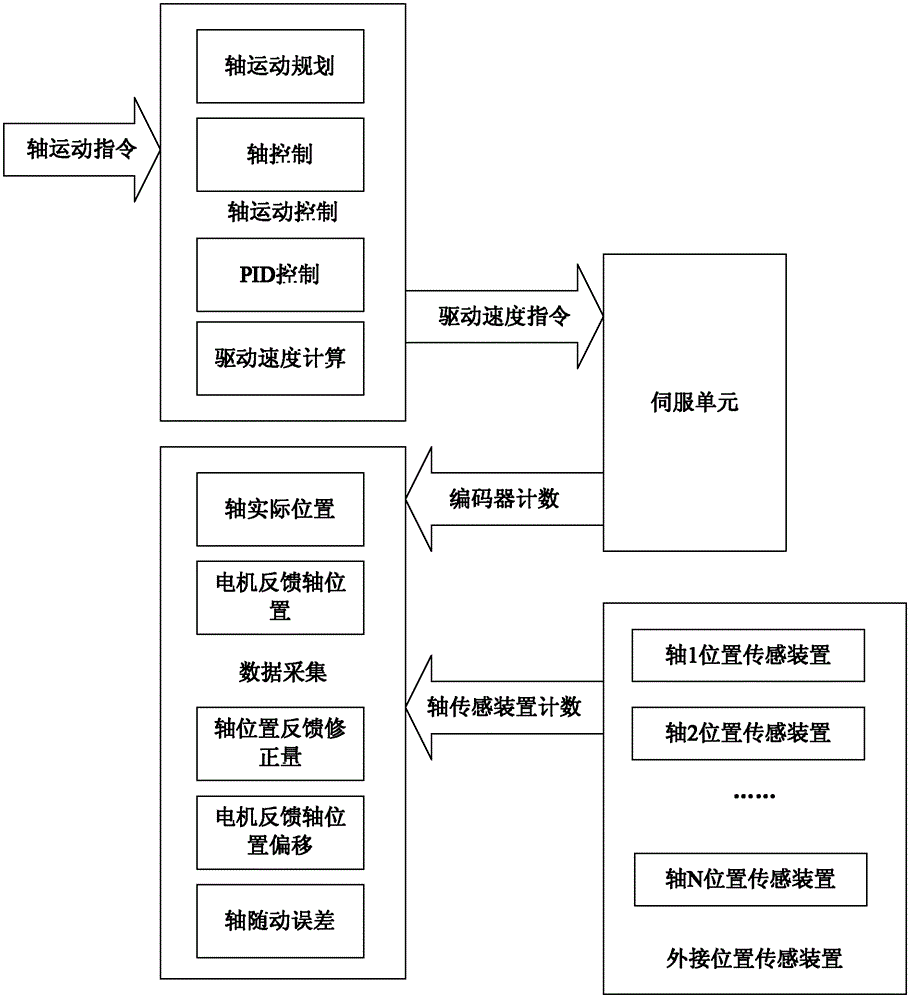
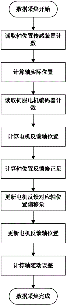
[0025] Axis motion control includes three parts: axis motion planning, axis control and PID control. Among them, the axis motion planning adopts the axis dynamic planning processing method of dual position feedback, and the axis motion planning is carried out for the axis motion command to form the axis speed setting value in the processing process. The control realizes the smooth rotation of the servo motor in the shaft transmission device.

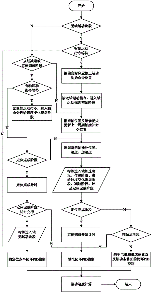
[0026] The axis motion planning includes 6 stages: 1) planning acceleration stage; 2) planning constant speed stage; 3) planning deceleration stage; 4) axis command feed speed change planning stage; 5) positioning completion stage; exercise phase. For different motion planning stages, the axis motion control method based on dual feedback of motor and machine tool position can be divided into different ...


PUM


Abstract

The invention relates to the control field of numerically-controlled machine tool and, is specific to a full closed-loop axial motion control method of dynamic correction motion interpolation of a shaft of a machine tool. The feedback of dynamic correction motion interpolation of the shaft of the machine tool is obtained through a belt circumscribed location sensing device. Countershaft motion instruction uses the feedback of a servo motor encoder and a machine tool location sensing device to perform a shaft motion planning and form a shaft speed set value in the processing procedure. The interpolation points of the shaft motion in the processing procedure are achieved by shaft controlling portion, and the smooth running of the servo motor in a shaft transmission device is achieved by PID (picture input device) control. The invention is well-adapted, the positioning accuracy and the repeated positioning accuracy of the machine tool can be ensured, the speed smoothness is high, dynamic nature is good and motion safety is high.

Description

technical field [0001] The invention relates to the field of numerical control machine tool control, in particular to a fully closed-loop axis motion control method for dynamic correction motion interpolation of a machine tool axis fed back by an external position sensing device. Background technique [0002] Nowadays, more and more CNC machine tools are widely used. At the same time, the positioning accuracy and repeat positioning accuracy of CNC machine tools are also increasing. The original semi-closed-loop control system with screw and encoder can no longer meet the needs of users. The semi-closed-loop control system cannot control the transmission error generated by the shaft transmission mechanism of the machine tool, the thermal deformation error generated by the transmission mechanism during high-speed operation, and the error caused by the wear of the transmission system during processing, and these errors have seriously affected the machining accuracy of CNC machin...

Claims


Application Information

Patent Timeline
Patent Type & Authority Patents(China)
IPC IPC(8): G05B19/19
Inventor 刘荫忠鲍玉凤杨东升
Owner 中国科学院沈阳计算技术研究所有限公司
Why Eureka
Try Eureka