Conducting cable connector

A technology of conductive cables and conductive connection blocks, applied in conductive connection, connection, clamping/spring connection, etc., can solve the problems of weak tolerance, easy damage of screw teeth, connection failure, etc., to achieve easy production and connection. Strong, simple structure

Active Publication Date: 2013-05-29
南京市高靠线路器材制造有限公司
View PDF16 Cites 5 Cited by
  • Summary
  • Abstract
  • Description
  • Claims
  • Application Information

AI Technical Summary

Problems solved by technology

The applicant has also applied to the State Intellectual Property Office for a variety of wiring structure patents, such as the invention patent with the application number 201010531991.8 "Strong and Weak Electric Joint Device Composed of Cone, Cone Hole and Its Deformation", in which the outer screw sleeve is pushed into the wedge Since there is no shrinkage joint on the wedge and no bevel at the push inlet, it is difficult to push the wedge in. Even if it is pushed in half, it is still a limited and unqualified product, and the force-bearing surface is limited to the thread. The contact surface of the port is still relatively weak, which makes the thread part easy to damage; in addition, the cable is limited to the hole diameter of the squeezed screw sleeve, and the hole can only be opened in a limited range, otherwise the wedge will come out and the connection will fail.
[0003] The above-mentioned various wiring structures still have disadvantages such as consumables, time-consuming, unstable installation caused by oxidation, and interface cracking due to temperature rise.

Method used


Image

  • Conducting cable connector
  • Conducting cable connector
  • Conducting cable connector

Examples


Embodiment Construction

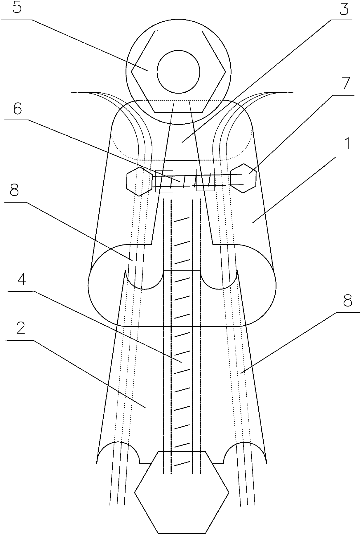
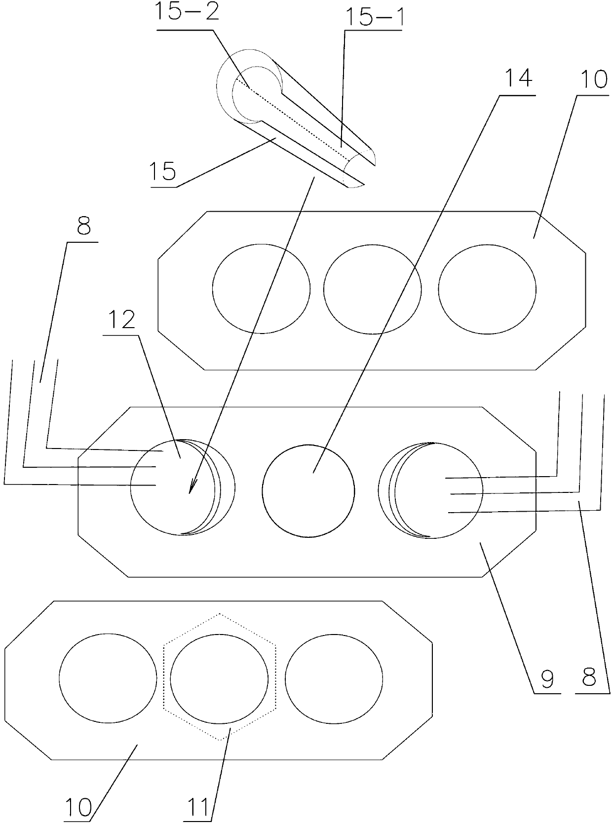
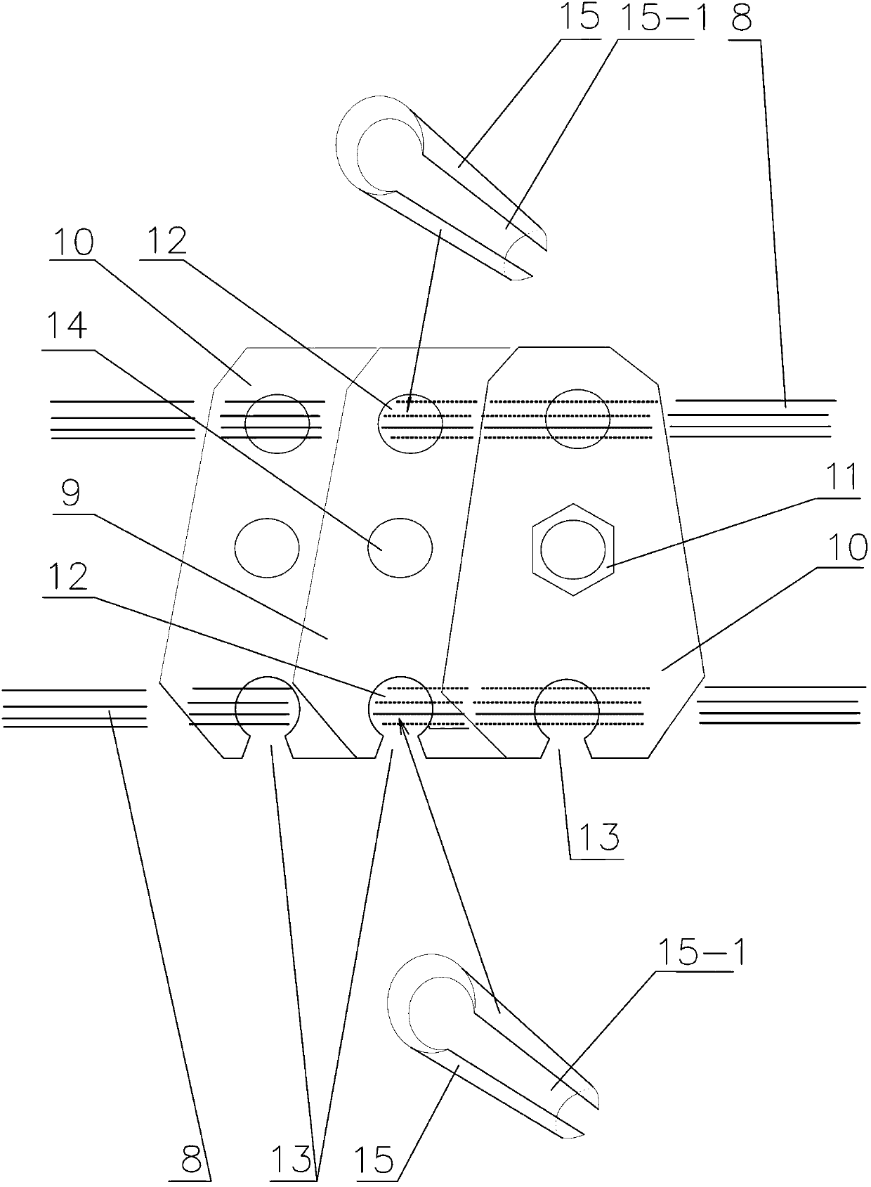
[0032] A number of technical solutions of the present invention will be further described below in conjunction with the accompanying drawings:

[0033] 1. The clamping part of the conductive cable connector of the present invention is a flat conductive inner cone sleeve 1 and a conductive outer cone sleeve 2 with outer arcs on both sides, and the conductive inner cone sleeve 1 is nested in the conductive outer cone sleeve 2 In the inner taper hole of the conductive outer tapered sleeve 2, an axial wire core enters the groove 3 on the upper plane of the conductive outer tapered sleeve 2, and the upper plane of the conductive outer tapered sleeve 2 on both sides of the conductive outer tapered sleeve 2 where the wire core enters the groove 3 is fixed with lugs. Set up a piercing hole; the squeeze bolt 4 is axially pierced in the conductive inner taper sleeve 1 and the conductive outer taper sleeve 2, the squeeze bolt 4 is screwed with the squeeze nut 5, and the hexagonal head of ...


PUM


Abstract

The invention discloses a conducting cable connector which comprises a clamping piece. The clamping piece comprises a conducting inner taper sleeve and a conducting outer taper sleeve which are mutually nested and squeezed, or conducting cone-shaped shrinking sleeves and a conducting connecting block, or conducting cone-shaped shrinking sleeves with axial shrinking grooves and a conducting wiring lug or a conducting wiring sleeve. The conducting cone-shaped shrinking sleeves and squeezing holes arranged on the conducting connecting block are matched to lock a cable core, and two oppositely arranged conducting cone-shaped shrinking sleeves are mutually squeezed in the conducting wiring lug or a sleeve hole of the conducting wiring sleeve to lock the cable core. A wiring mode of strong-pressure squeezing of a conducting cone is adopted, and the conducting cable connector is simple in structure, easy to manufacture, fast to install, firm to connect, resistant to lightning, insulating to electric arc, resistant to fire outbreak and faults and long in service life, can be recycled, saves energy, and can be used for remote transmission of electric power, wiring in the field of various alternating-current and direct-current motors, electrical appliances, distribution boxes, welding machines and electric power and power grids, and safe and reliable connection of vehicles, ships, satellite cables and small lines.

Description

(1) Technical field: [0001] The invention relates to a connection mechanism for conductive wires and cables, in particular to a conductive cable connector. (2) Background technology: [0002] There are many ways to connect wires and cables, such as wire twisting, copper tube oil pressure, and bullet shooting compression. The applicant has also applied to the State Intellectual Property Office for a variety of wiring structure patents, such as the invention patent with the application number 201010531991.8 "Strong and Weak Electric Joint Device Composed of Cone Cone Hole and Its Deformation", in which the outer screw sleeve is pushed into the wedge Since there is no shrinkage joint on the wedge and no bevel on the push inlet, it is difficult to push the wedge in. Even if it is pushed in half, it is still a limited and unqualified product, and the force-bearing surface is limited to the thread. The contact surface of the port is still relatively weak, which makes the thread p...

Claims


Application Information

Patent Timeline
Patent Type & Authority Applications(China)
IPC IPC(8): H01R9/03H01R4/50
Inventor 甘国强
Owner 南京市高靠线路器材制造有限公司
Why Eureka
Try Eureka