
Method for manufacturing propeller shaft special for ship with electro slag remelting-fusion welding process

A marine propeller and electroslag remelting technology, which is applied in the field of heavy equipment manufacturing, can solve the problems of low material utilization, high production power consumption, environmental pollution, etc., and achieve high material utilization, low cost, and improved mechanical properties. Effect

Inactive Publication Date: 2013-06-05
天津中炎科技有限公司
View PDF0 Cites 2 Cited by
  • Summary
  • Abstract
  • Description
  • Claims
  • Application Information

AI Technical Summary

Problems solved by technology

The traditional production of propeller shaft blanks adopts full-fiber extrusion forging, but the forged propeller shaft has high power consumption, low material utilization rate, high cost, and pollutes the environment

Method used


Image

  • Method for manufacturing propeller shaft special for ship with electro slag remelting-fusion welding process
  • Method for manufacturing propeller shaft special for ship with electro slag remelting-fusion welding process
  • Method for manufacturing propeller shaft special for ship with electro slag remelting-fusion welding process

Examples


Embodiment 1

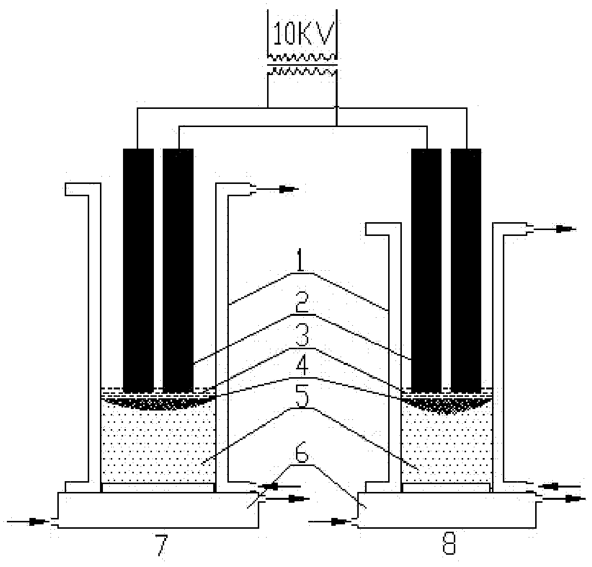
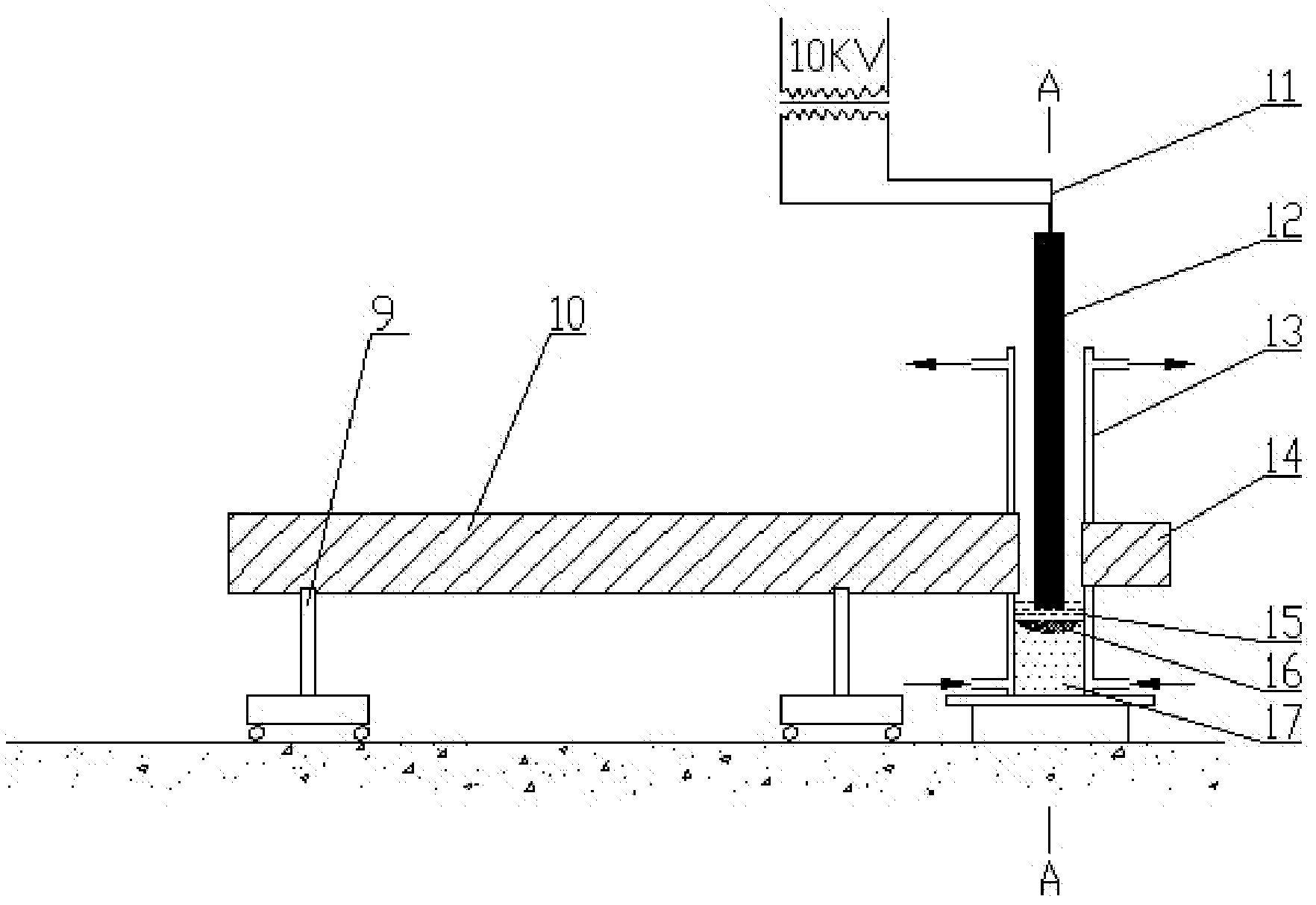
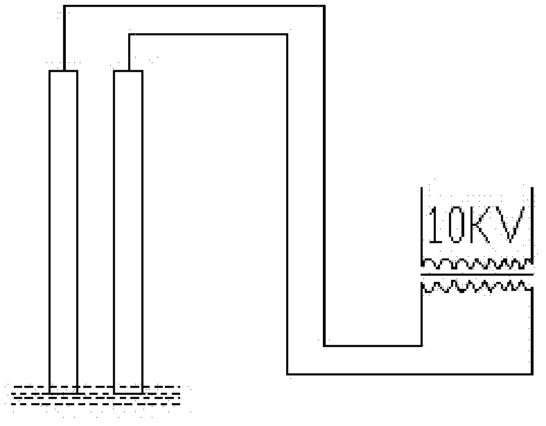
[0028] Embodiment 1: a kind of method of manufacturing marine propeller shaft with electroslag remelting-fusion welding process is characterized in that it comprises electroslag remelting process and electroslag welding process (see Figure 1-3 ), which consists of the following steps:

[0029] (1) Adjust and install the special-shaped copper water-cooled crystallizer I1;

[0030] (2) Insert the two ends of the two consumable electrodes I2 into the crystallizer I1;

[0031] (3) adding the pre-dried and melted ternary slag system I3 into the crystallizer I1;

[0032] (4) Power transmission, the current is connected to the ternary slag system I3 through the consumable electrode I2, and the slag pool completes the conversion of electric energy and heat energy through the current, and controls the outlet water temperature of the crystallizer I1 to not exceed 70°C;

[0033] (5) The consumable electrode I2 slowly melts in the ternary slag system I3 to form molten steel droplets, a...

Embodiment 2

[0047] Embodiment 2: a kind of method of manufacturing marine propeller shaft with electroslag remelting-fusion welding process is characterized in that it comprises electroslag remelting process and electroslag welding process (see Figure 1-3 ), which consists of the following steps:

[0048] (1) Adjust and install the special-shaped copper water-cooled crystallizer I1;

[0049] (2) Insert the two ends of the two consumable electrodes I2 into the crystallizer I1;

[0050] (3) adding the pre-dried and melted ternary slag system I3 into the crystallizer I1;

[0051] (4) Power transmission, the current is connected to the ternary slag system I3 through the consumable electrode I2, and the slag pool completes the conversion of electric energy and heat energy through the current, and controls the outlet water temperature of the crystallizer I1 to not exceed 70°C;

[0052](5) The consumable electrode I2 slowly melts in the ternary slag system I3 to form molten steel droplets, an...


PUM


Abstract

A method for manufacturing a propeller shaft special for a ship with an electro slag remelting-fusion welding process is characterized by comprising an electro slag remelting process and an electro slag fusion welding process. The method for manufacturing the propeller shaft special for the ship with the electro slag remelting-fusion welding process has the advantages that production equipment is low in manufacturing and use cost, low in power dissipation and high in material utilization; crystallization direction is easy to control in the process, remelted metal is pure, compact in organization, uniform in components, accurate in size and glossy in appearance; purity of the metal is higher than that of the metal which is though electric-arc furnace external refining, physicochemical indexes of materials are equal to those of a forging propeller shaft and satisfy the demand of a classification society; an propeller shaft through electro slag remelting is low in cost; and appropriate quantity of rare earth is added in the process of electro slag remelting casting to improve mechanical properties of castings.

Description

(1) Technical field: [0001] The invention belongs to the field of heavy equipment manufacturing industry, in particular to a method for manufacturing a marine propeller shaft by an electroslag remelting-fusion welding process. (two) background technology: [0002] The propeller shaft is an important part of the ship's propulsion shaft system, and plays an important role in the ship's power design and manufacturing. The traditional production of propeller shaft blanks adopts full-fiber extrusion forging, but forged propeller shafts have high power consumption, low material utilization, high cost, and pollute the environment. The use of electroslag remelting-fusion welding technology to manufacture marine propeller shafts saves raw materials due to precise dimensions and small machining allowances. At the same time, due to the low cost of manufacturing and using production equipment, production costs are reduced, which meets the national energy conservation and emission reduct...

Claims


Application Information

Patent Timeline
IPC IPC(8): B22D23/10
Inventor 戴思源
Owner 天津中炎科技有限公司
Learn More