Polyhedron milling head

A technology of milling cutter head and polyhedron, which is applied in the direction of metal processing machinery parts, driving devices, metal processing equipment, etc., can solve problems such as positioning errors, achieve the effects of reducing errors, improving work efficiency, and increasing enterprise benefits

Inactive Publication Date: 2013-06-05
NINGBO VICTORY PRECISION MACHINERY
View PDF6 Cites 1 Cited by
  • Summary
  • Abstract
  • Description
  • Claims
  • Application Information

AI Technical Summary

Problems solved by technology

Multiple faces of a complex part can be processed by one clamping to solve the problem of positioning errors caused by repeated clamping of parts during milling machine processing

Method used


Image

  • Polyhedron milling head

Examples


Embodiment Construction

[0022] The principles and features of the present invention will be described in detail below in conjunction with the accompanying drawings, and the examples given are only used to explain the present invention and are not intended to limit the scope of the present invention.

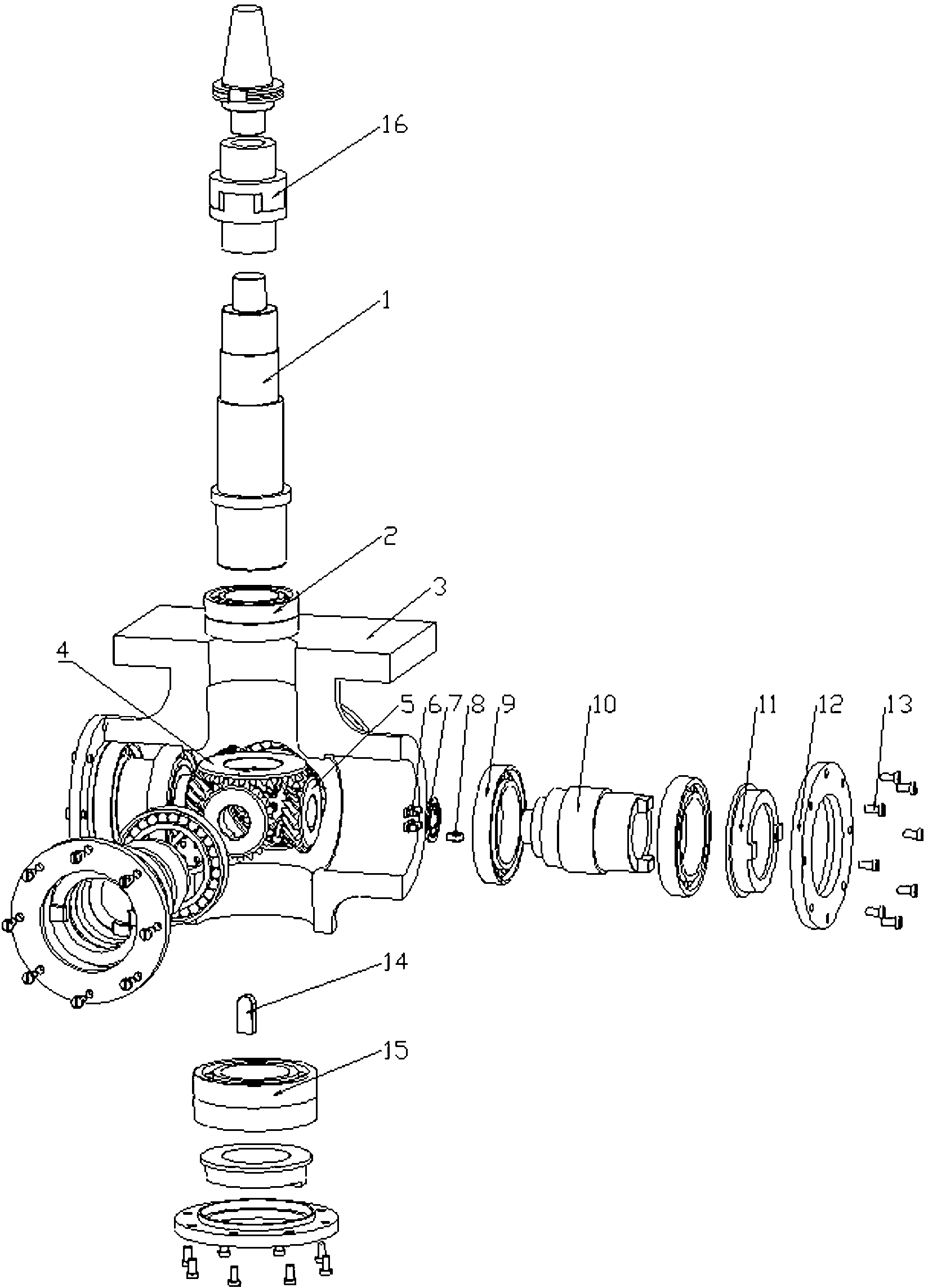
[0023] Such as figure 1 As shown, the polyhedral milling cutter head described in the embodiment of the present invention includes a main shaft 1 and a housing 3. The upper end of the main shaft 1 is connected to a taper shank through a quincunx coupling 16, and the taper shank can be directly installed on the machine tool spindle. The lower end of the main shaft 1 is equipped with a first angular contact ball bearing 2, the first spiral bevel gear 4 is installed on the main shaft 1, and the first spiral bevel gear 4 is surrounded by a gear that meshes with the first spiral bevel gear 4. The second spiral bevel gear 5 is uniformly distributed at a fixed angle around the first spiral bevel gear 4 accordi...


PUM


Abstract

The invention relates to a polyhedron milling head. The polyhedron milling head comprises a main shaft and a shell body. The main shaft is provided with a first gleason spiral bevel gear. Four second gleason spiral bevel gears are uniformly arranged around the first gleason spiral bevel gear in a 90-degree mode and meshed with the first gleason spiral bevel gear. Each second gleason spiral bevel gear is connected with a transmission shaft, one end of the transmission shaft is located through a round end cover shaft axially, and the other end of the transmission shaft is located through a flange plate axially. A snap ring is connected between the transmission shaft and the flange plate through fine threads. The polyhedron milling head has the advantages of being capable of being used on various standard milling machines in a supporting mode, safe, reliable, convenient to disassemble and assemble, strong in adaptability, and capable of improving dimensional accuracy of machined parts greatly.

Description

technical field [0001] The invention belongs to an auxiliary tool for a milling machine in mechanical manufacturing, and in particular relates to a polyhedron milling cutter head. Background technique [0002] With the rapid development of social production and science and technology, profound changes have taken place in machinery manufacturing technology, and mechanical products are becoming more and more sophisticated and frequently modified. The development of machinery manufacturing technology is developing in the direction of high speed, precision, high efficiency, serialization and compounding, and the precision requirements of products are also increasing day by day. [0003] For a long time, for milling machines to process multiple surfaces of a complex part, it is necessary to design multiple different fixtures. During processing, the workpiece needs to be turned over and positioned multiple times. Cause positioning errors, seriously affect the dimensional accuracy...

Claims


Application Information

Patent Timeline
IPC IPC(8): B23Q5/04
Inventor 陈明伟李杰陈春
Owner NINGBO VICTORY PRECISION MACHINERY
Why Eureka
Try Eureka