Mould locking device for bottle blowing machine

A machine locking and mold locking technology, applied in the field of mold locking devices of blow molding machines, can solve the problems of low energy consumption, large mold locking pressure, long mold locking stroke, etc., and achieves high work efficiency, low energy consumption, and opening and closing speed. quick effect

Inactive Publication Date: 2013-06-05
GUANGDONG LESHAN INTELLIGENT EQUIP CORP LTD
View PDF6 Cites 4 Cited by
  • Summary
  • Abstract
  • Description
  • Claims
  • Application Information

AI Technical Summary

Problems solved by technology

However, this mode of clamping requires very precise adjustment of the length of the support rod. In addition, the long-term friction between the groove and the gate will easily cause wear and tear, resulting in inaccurate clamping position, that is, the clamping stroke is too short and there is still a gap between the molds. Or the clamping stroke is too long, after the mold has been completely closed, but the gate cannot be inserted into the groove to lock the mold, etc.
Furthermore, this mode of clamping does not continuously apply force to the mold to maintain the clamping pressure. The mold is easy to loosen and the clamping pressure is not tight. large clamping mechanism

Method used


Image

  • Mould locking device for bottle blowing machine
  • Mould locking device for bottle blowing machine

Examples


Embodiment Construction

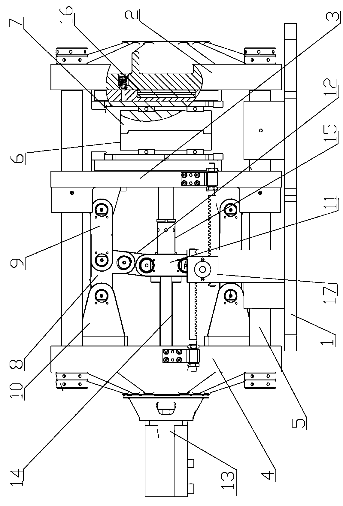
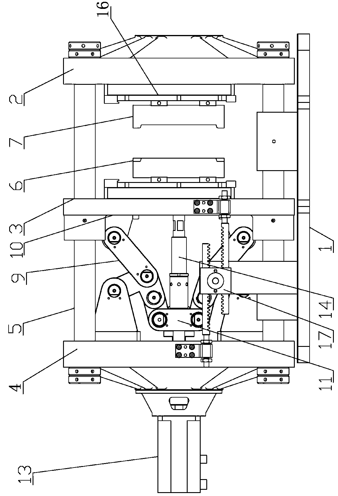
[0017] Hereinafter, the present invention will be further explained in detail with reference to the drawings. A mold clamping device for a bottle blowing machine includes a mold base 1, a front mold 2, a middle mold 3, a rear mold 4, and a guide post 5 that penetrates between the mold bases. The middle mold 3 is installed The left mold 6, the right mold 7 is installed on the front mold 2, the middle mold 3 and the rear mold 4 are symmetrically distributed and hinged hinged mold clamping mechanism, characterized in that: the right mold 7 and the front mold 2 A clamping and pressing mechanism 16 is installed between.

[0018] The clamping and pressing mechanism 16 is a flat piston cylinder.

[0019] The flat piston cylinder of the clamping and pressing mechanism 16 is a pneumatic cylinder.

[0020] The flat piston cylinder of the clamping and pressing mechanism 16 is a hydraulic cylinder.

[0021] The articulated mold clamping mechanism is connected to the connecting block 10 by two a...


PUM


Abstract

A mould locking device for a bottle blowing machine comprises a mould frame base, a front mould plate, a middle mould plate, a rear mould plate and a guide column, wherein the front mould plate, the middle mould plate and the rear mould plate are arranged on the mould frame base, the guide column penetrates through all mould plates, a left mould is positioned on the middle mould plate, a right mould is arranged on the front mould plate, and a hinged mould locking mechanism is symmetrically distributed and movably hinged between the middle mould plate and the rear mould plate. The mould locking device is characterized in that a flat piston cylinder is installed between the right mould and the front mould plate. The hinged mould locking mechanism is formed by two hinge rods which are movably hinged with a connection rod A and a connection block, the two hinge rods are movably hinged through a carriage, and a servo motor driving roller lead screw is in screw connection with a nut on the carriage. The mould locking device has the advantages of using an ordinary air cylinder or a hydraulic oil cylinder or even the servo motor push lever principle to open and close a mould so as to be quick in opening and closing speed and small in energy consumption; and individually using a mould locking air cylinder with large cylinder diameter and short stroke to lock the mould so as to be large in mould locking force, high in work efficiency and the like.

Description

Technical field [0001] The invention relates to a stretch blow molding equipment, in particular to a mold clamping device of a bottle blowing machine. Background technique [0002] Most hollow plastic containers such as cola bottles and mineral water bottles are made of injection molding. The process of the entire working line of the bottle blowing machine is to first transfer the preform to the preform mounting end of the preform holder, then heat or preheat the preform, and then enter the blowing and stretching mechanism, and the mold is closed after the mold is closed. Stretching and blow molding are carried out in the blowing mechanism, and finally the formed bottle is unloaded from the blowing machine. Therefore, it is necessary to repeatedly open and close the mold during the production process. The existing plastic bottle blowing machine opening and closing mold clamping device has a working cylinder that uses the combination of air pressure and hydraulic pressure as the ...

Claims


Application Information

Patent Timeline
Patent Type & Authority Applications(China)
IPC IPC(8): B29C49/56
Inventor 王树辉刘炳冠
Owner GUANGDONG LESHAN INTELLIGENT EQUIP CORP LTD
Why Eureka
Try Eureka