Process equipment for oily sludge

A technology for treating equipment and sludge, applied in sludge treatment, water/sludge/sewage treatment, chemical instruments and methods, etc., can solve problems such as oil sludge pollution, high treatment costs, harsh operating conditions, etc., and achieve construction investment The effect of reduction, reduced floor area, and high degree of mechanization

Inactive Publication Date: 2013-06-05
XIAN REJE BIOLOGICAL TECH
View PDF0 Cites 3 Cited by
  • Summary
  • Abstract
  • Description
  • Claims
  • Application Information

AI Technical Summary

Problems solved by technology

[0002] For the treatment of oily sludge, a large number of research practices have been carried out at home and abroad, and methods such as concentration, flotation, extraction, and incineration are usually used, but most of them have the following problems: (1) High energy consumption and high treatment cost High responsibility; (2) The process is complex and the operating conditions are harsh; (3) The resource recovery rate is low
However, a suitable method with a high recovery rate has not been developed technically; (4) The oily sludge treatment technology is not thorough, which is likely to cause secondary pollution
The oil separation in oily sludge is not complete. Although the oil content in the oily sludge is reduced, the purpose of oily sludge separation is not fully achieved, and the separated oily sludge will still cause pollution; as a chemical agent for oily sludge separation, it may also cause environmental impact and harm

Method used


Image

  • Process equipment for oily sludge

Examples


Embodiment Construction

[0020] The present invention will be further described below in conjunction with the accompanying drawings and examples, but the present invention is not limited thereto.

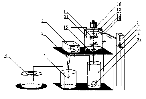
[0021] like figure 1 As shown, a treatment equipment for oily sludge includes a sludge cleaning tank 1, a mud tank 2, a mud tank 4, a rotary jet separator 3, a controller 5, a centrifuge 6, a clear water tank 7, and the top of the cleaning tank 1 An annular overflow weir 12 is set, and a groove type oil separation tank 13 is formed between the wall of the cleaning tank 1, which communicates with the clear water tank 7 through the drain valve 14, and the cleaning tank 1 is provided with an agitator 11 and a temperature sensor 51 (reflecting that the cleaning tank 1 Inner temperature], the temperature sensor 51 is electrically connected with the controller 5; the mud tank 2 is installed under the cleaning tank 1, the mud tank 2 is connected with the swirl jet separator 3 pipelines, and the mud tank 4 is arran...


PUM


Abstract

The invention provides process equipment for oily sludge. The process equipment comprises an oily sludge cleaning tank 1, a sludge containing tank 2, a rotary jet flow separator 3, a sludge containing tank 4, a controller 5, a centrifugal machine 6 and a clean water sink 7. An annular downflow weir 12 is arranged above the oily sludge cleaning tank 1, a groove type oil separation tank 13 is formed between the downflow weir 12 and the wall of the oily sludge cleaning tank 1, the oily sludge cleaning tank 1 is communicated with the clean water sink 7 through a drain valve 14, a stirrer 11 and a temperature sensor 51 are arranged in the oily sludge cleaning tank 1, the temperature sensor 51 is electrically connected with the controller 5, the sludge containing tank 2 is installed below the oily sludge cleaning tank 1, the sludge containing tank 2 is connected with a pipeline of the rotary jet flow separator 3, the sludge containing tank 4 is arranged below the rotary jet flow separator 3, the sludge containing tank 4 is communicated with a pipeline of the centrifugal machine 6, a slush pump 21 is installed in the sludge containing tank 2, and a clean water pump 71 is installed in the clean water sink 7. The process equipment for the oily sludge is complete in design, high in mechanization degree, capable of reducing device construction investment by 50% under the same sludge process capacity, reducing occupied space by 60% and achieving the purposes of stabilization, harmless, minimization and reclamation of the sludge effectively.

Description

technical field [0001] The invention belongs to the technical field of oilfield sludge treatment, and in particular relates to treatment equipment for oily sludge. Background technique [0002] For the treatment of oily sludge, a large number of research practices have been carried out at home and abroad, and methods such as concentration, flotation, extraction, and incineration are usually used, but most of them have the following problems: (1) High energy consumption and high treatment cost High responsibility; (2) The process is complex and the operating conditions are harsh; (3) The resource recovery rate is low. As oily sludge (tank bottom sludge and landing oil), the oil content is as high as 20% to 30%. The oil in the oily sludge is recovered to make the oily sludge a resource. But at present, a suitable method with high recovery rate has not been developed technically; (4) The oily sludge treatment technology is not thorough, which is easy to cause secondary polluti...

Claims


Application Information

Patent Timeline
Patent Type & Authority Applications(China)
IPC IPC(8): C02F11/00
Inventor 陈富林
Owner XIAN REJE BIOLOGICAL TECH
Why Eureka
Try Eureka