Flow passage type sewage heat exchanger

A heat exchanger and runner type technology, which is applied in the field of runner type sewage heat exchangers, can solve the problems of large welding workload, high cost, fatigue damage of weld seams, etc., and achieves low manufacturing cost, reasonable structure, flow channel smooth effect

Active Publication Date: 2013-06-05
HIT HARBIN INST OF TECH KINT TECH
View PDF8 Cites 5 Cited by
  • Summary
  • Abstract
  • Description
  • Claims
  • Application Information

AI Technical Summary

Problems solved by technology

However, the sewage heat exchanger with this structure has two fatal shortcomings: one is that during the manufacturing process of this heat exchanger, the welding workload is huge and the cost is too high; It is prone to fatigue damage, causing leakage and affecting social benefits

Method used


Image

  • Flow passage type sewage heat exchanger
  • Flow passage type sewage heat exchanger
  • Flow passage type sewage heat exchanger

Examples


Embodiment Construction

[0033] The present invention will be described in further detail below in conjunction with the accompanying drawings and embodiments.

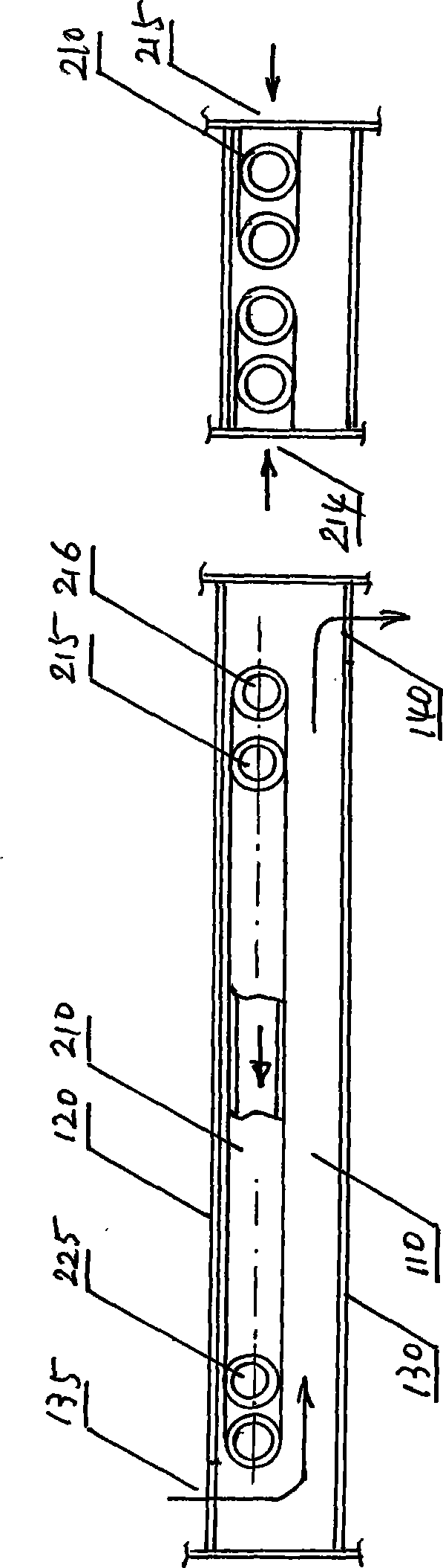
[0034] figure 1 The basic principle diagram of the embodiment of the channel type sewage heat exchanger of the present invention is given.

[0035] The basic principle of the embodiment of the flow channel type sewage heat exchanger of the present invention is as follows: figure 1 , indicating two channels of sewage and clean water, and the sewage and clean water conduct convective heat exchange.

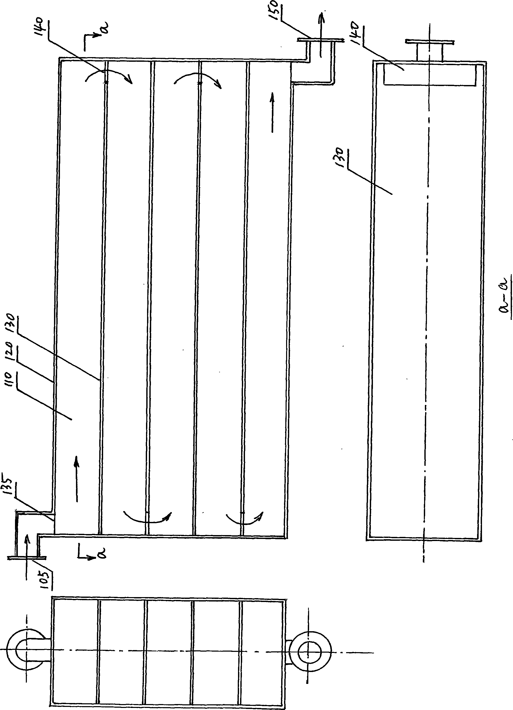
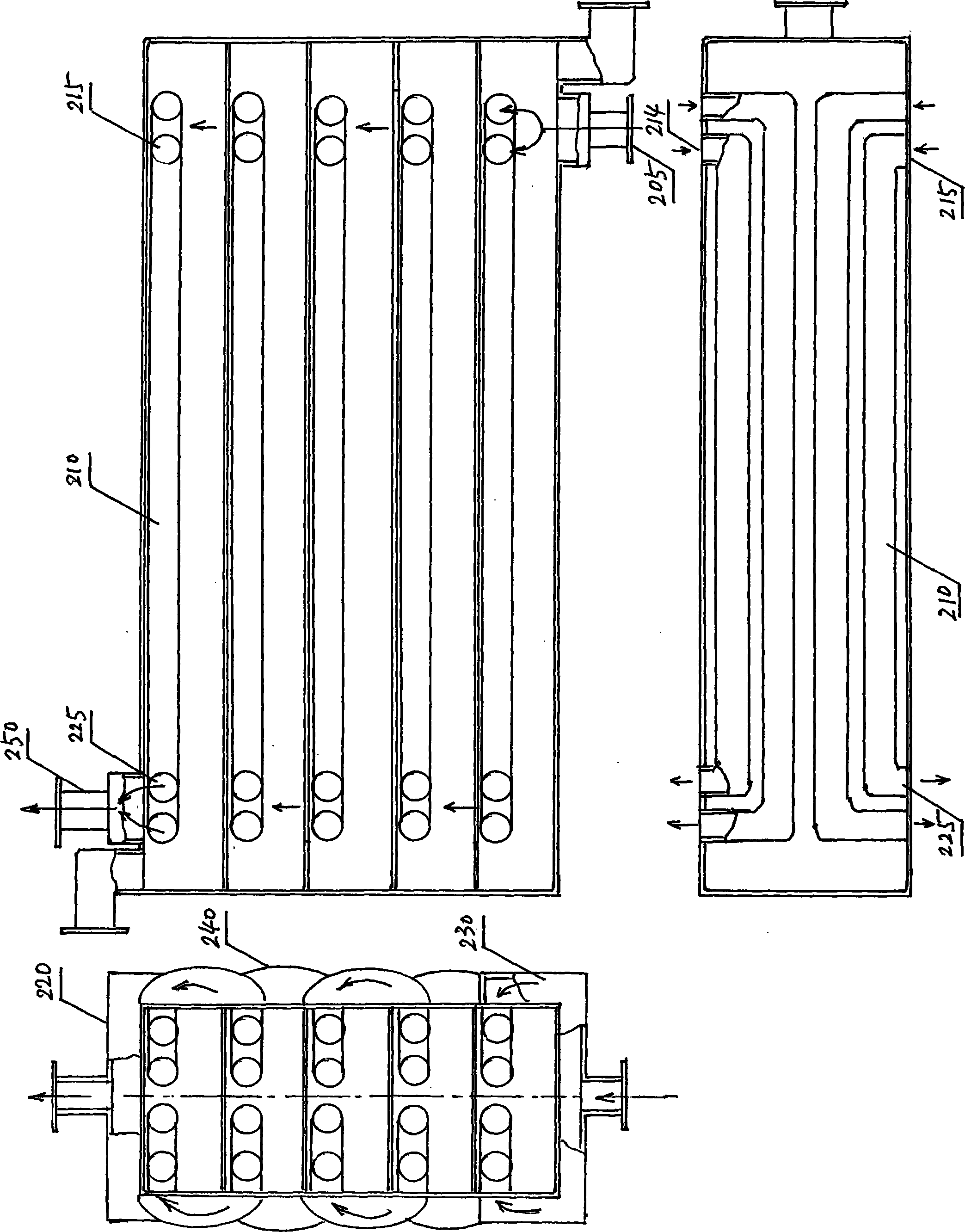
[0036] The sewage flow channel is a sewage pipeline 110 with a rectangular cross-section formed by the top plate 120 and the bottom plate 130 of the flow channel, as well as side plates and end plates. The water inlet 135 of the sewage pipeline 110 is at one end of the top plate 120 , and the water outlet 140 of the sewage pipeline 110 is at the other end of the bottom plate 130 .

[0037] In the sewage pipeline 110, a clean water flow channel is...


PUM


Abstract

The invention provides a flow passage type sewage heat exchanger which structurally comprises a box body, a sewage flow passage, a clear water flow passage, a dirt removing door and a base. Sewage and clear water respectively flow in the flow passages arranged inside the box body and heat is exchanged through a dividing wall. The clear water flow passage is composed of a plurality of circular heat transmission tubes, arranged inside the sewage flow passage with a rectangular cross section, and tightly attached to the lower surface of a top plate of the sewage flow passage. The sewage flow passage comprises a sewage inlet, a sewage pipeline and a sewage outlet. The sewage enters the heat exchanger from the sewage inlet, enters the sewage pipeline from a water inlet at one end of the top plate of the sewage pipeline, flows out from a water outlet at the other end of a bottom plate, and finally flows out from the sewage outlet. The clear water flow passage comprises a clear water inlet, an inlet water distributive tank, clear water pipelines, a tile-shaped plate, an outlet collection tank and a clear water outlet. The clear water enters the heat exchanger from the clear water inlet, passes the inlet water distributive tank, enters the clear water pipeline, passes the tile-shaped plate, enters another clear water pipeline, and finally passes an outlet collection tank and flows out from the clear water outlet.

Description

technical field [0001] The invention relates to heat exchange equipment, in particular to a channel type sewage heat exchanger. Background technique [0002] Using urban sewage as a cold and heat source to heat and air-condition buildings can directly reduce the consumption of other scarce energy sources, and at the same time achieve the purpose of waste utilization. It is an important measure for resource regeneration, development of circular economy, construction of a conservation-minded society, and a friendly environment. . [0003] The sewage source heat pump relies on the physical state cycle of the refrigerant inside the heat pump unit. In winter, heat is absorbed from the sewage and heated by the heat pump unit to heat the building. In summer, the heat in the building is transferred to the sewage through the heat pump unit to achieve cooling. Sewage replaces the cooling tower, which has the outstanding advantages of high efficiency, energy saving, environmental prot...

Claims


Application Information

Patent Timeline
Patent Type & Authority Applications(China)
IPC IPC(8): F28D7/00F28F21/08
Inventor 尚德敏李金峰李伟张勇
Owner HIT HARBIN INST OF TECH KINT TECH
Why Eureka
Try Eureka