Power distribution station monitoring system
A monitoring system and power distribution station technology, applied in the direction of closed-circuit television system, electrical program control, comprehensive factory control, etc., can solve the problem that data communication transmission cannot meet the requirements of video image transmission, the amount of data cannot be obtained above 2M, and the transmission bandwidth Insufficient problems, to achieve the effect of reducing the amount of data transmission, small intervals, and accurate monitoring results
- Summary
- Abstract
- Description
- Claims
- Application Information
AI Technical Summary
Problems solved by technology
Method used
Image
Examples
Embodiment 1
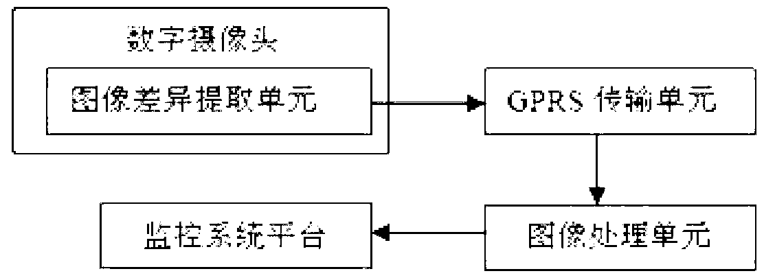
[0040] The distribution substation room monitoring system described in this embodiment, such as figure 1As shown, it includes: a digital camera, which is used to monitor the video picture in the power distribution station room, and has a uniquely determined IP address; an image difference extraction unit, built in the digital camera, receives the video picture monitored by the camera For each frame of image, analyze the difference between two frames of images within a set time period, and output the difference part data of the image group with difference; the transmission unit is connected with the image difference extraction unit, and receives the image group with difference. The starting point of the set time period, the first frame image output by the digital camera; simultaneously receive the difference part data of the difference group image output by the image difference extraction unit; and the first frame image and the output of the difference part data; in this embodi...
Embodiment 2
[0043] This embodiment makes the following improvements on the basis of Embodiment 1. The image difference extraction unit includes: an image partition module, which is used to obtain M blocks for each frame of image according to the same partition method, M is a natural number, and each The block is a pixel matrix composed of pixels, and a parameter is configured for each pixel according to the brightness of each pixel, and the parameters corresponding to all pixels in each block form a block array; the image comparison module selects the qth Compare all block arrays in the frame image (1m>1) block arrays and the mth block array in the (q-1)th frame image, then only output the mth block array of the qth frame image; if the qth frame image All block arrays in the (q-1)th frame image are the same as all block arrays in the (q-1)th frame image, and no signal is output; the image processing unit is based on all block arrays in the (q-1)th frame image, Replace the m-th block array...
Embodiment 3
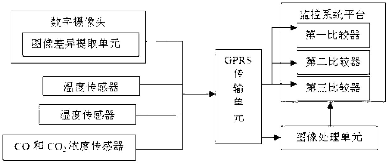
[0047] This embodiment is on the basis of embodiment 1 or embodiment 2, as shown in Figure 3, it further comprises temperature sensor, is used for real-time monitoring temperature value in the substation room; The monitoring system platform transmits through the GPRS The unit receives and displays the data collected by the temperature sensor; the monitoring system platform has a built-in first comparator and a temperature alarm threshold; the first comparator compares the temperature value in the monitoring distribution station room with the temperature Alarm threshold, when the temperature value in the monitored distribution substation room is equal to or greater than the temperature alarm threshold, the monitoring system platform sends an alarm message.
[0048] Furthermore, it includes a humidity sensor for real-time monitoring of the humidity value in the substation room; the monitoring system platform receives and displays the data collected by the humidity sensor through ...
PUM
 Abstract
Description
Claims
Application Information
 - R&D
- Intellectual Property
- Life Sciences
- Materials
- Tech Scout
- Unparalleled Data Quality
- Higher Quality Content
- 60% Fewer Hallucinations
Browse by: Latest US Patents, China's latest patents, Technical Efficacy Thesaurus, Application Domain, Technology Topic, Popular Technical Reports.
© 2025 PatSnap. All rights reserved.Legal|Privacy policy|Modern Slavery Act Transparency Statement|Sitemap|About US| Contact US: help@patsnap.com


