
High-power chip resistor

A chip resistor, high-power technology, applied in the direction of resistors, resistor parts, resistor terminals/electrodes, etc., can solve the problems of difficult automation, easy heating of PCB boards, high product defect rate, etc., to improve welding efficiency, Avoid lead wire connection, the effect of soldering stability

Inactive Publication Date: 2013-06-05
东莞市晴远电子有限公司
View PDF4 Cites 3 Cited by
  • Summary
  • Abstract
  • Description
  • Claims
  • Application Information

AI Technical Summary

Problems solved by technology

This kind of resistance can meet the needs to a certain extent, but its disadvantages are: when the resistance is welded, manual insertion is required, which is time-consuming, and when there is a floating height requirement, it is difficult to realize automation; when the resistance is close to the PCB board, the PCB board is easy to heat up , it is not easy to pass the safety test; resistance welding requires wave soldering, the welding is unstable, and the product defect rate is high

Method used


Image

  • High-power chip resistor

Examples


Embodiment Construction

[0014] The best embodiments of the present invention will be described in detail below in conjunction with the accompanying drawings.

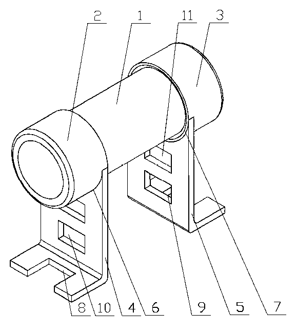
[0015] Such as figure 1 As shown, the high-power chip resistor of the present invention includes a resistor body 1, a left end cap 2, a right end cap 3, a left bracket 4 and a right bracket 5, and the left end cap 2 is installed on the left end of the resistor body 1 and connected to the lead-out end at the left end , the right end cap 3 is installed on the right end of the resistor body 1 and connected to the lead-out end at the right end, the left bracket 4 is fixed on the bottom of the left end cap 2, the right bracket 5 is fixed on the bottom of the right end cap 3, through the left end cap 2 and the right end cap 3 It is connected to the leading end of the resistor body 1 and supported by the left bracket 4 and the right bracket 5, and is connected to the PCB board through the left bracket 4 and the right bracket 5, which avoids the lead ...


PUM


Abstract

The invention discloses a high-power chip resistor which comprises a resistor body and also comprises end caps and a bracket, wherein the end caps are arranged at two ends of the resistor body and are connected with outgoing ends of the resistor body, the bracket is fixed at the bottoms of the end caps. According to the high-power chip resistor, the end caps are connected with the outgoing ends of the resistor body and are supported by the bracket and are connected with a PCB (Printed Circuit Board) through the bracket, thus the lead connection of the conventional resistor is avoided, the welding efficiency of the chip resistor is increased, and the working hour is saved; and meanwhile, after the resistor floats, the heat radiating space is enlarged, a good heat radiating property is achieved, heat can not be transmitted to the PCB to ensure that the PCB is easily demonstrated by safety requirements, and the space of the PCB is saved. In addition, after the resistor floats, a reflow soldering process can be used, and is stable in welding, and thus the yield of products is increased.

Description

technical field [0001] The invention relates to a high-power chip resistor and belongs to the technical field of resistors. Background technique [0002] As an important electronic component, resistors are widely used in electrical equipment. Most of the current resistors include a resistor body and a lead wire, and the lead wire is connected to the lead end of the resistor body to form a resistor. This kind of resistance can meet the needs to a certain extent, but its disadvantages are: when the resistance is welded, manual insertion is required, which is time-consuming, and when there is a floating height requirement, it is difficult to realize automation; when the resistance is close to the PCB board, the PCB board is easy to heat up , It is not easy to pass the safety test; resistance welding requires wave soldering, the welding is unstable, and the product defect rate is high. Contents of the invention [0003] In order to overcome the shortcomings of the prior art,...

Claims


Application Information

Patent Timeline
IPC IPC(8): H01C1/14H01C1/014H01C1/08
Inventor 罗凯
Owner 东莞市晴远电子有限公司
Learn More