Supercharge Your Innovation With Domain-Expert AI Agents!

Ion implanter

A technology of ion implanter and reaction chamber, which is applied in the manufacture of electrical components, circuits, semiconductors/solid-state devices, etc. It can solve the problems of high temperature, complex principle and structure, expensive purchase and maintenance, and achieve the effect of simple structure

Inactive Publication Date: 2013-06-05
INST OF MICROELECTRONICS CHINESE ACAD OF SCI
View PDF4 Cites 3 Cited by
  • Summary
  • Abstract
  • Description
  • Claims
  • Application Information

AI Technical Summary

Problems solved by technology

This type of ion implanter has the advantages of high purity of implanted ions and precise control of implant dose, but there are also some shortcomings: 1. The principle and structure are relatively complicated, and the purchase and maintenance are expensive; 2. The size of the substrate is too small to Large-area injection; 3. The temperature required for activation after injection is relatively high
Compared with IC manufacturing, although there are similarities in the process, the newly developed large-area implantation process puts forward new requirements for the implanter: 1. The area of ​​the substrate is larger; 2. The materials of the substrate are different. The process temperature should not be too high; 3. The implantation depth is low, and the ion energy demand is reduced; 4. The purity and uniformity requirements of the implanted particles are reduced

Method used


Image

  • Ion implanter

Examples


Embodiment Construction

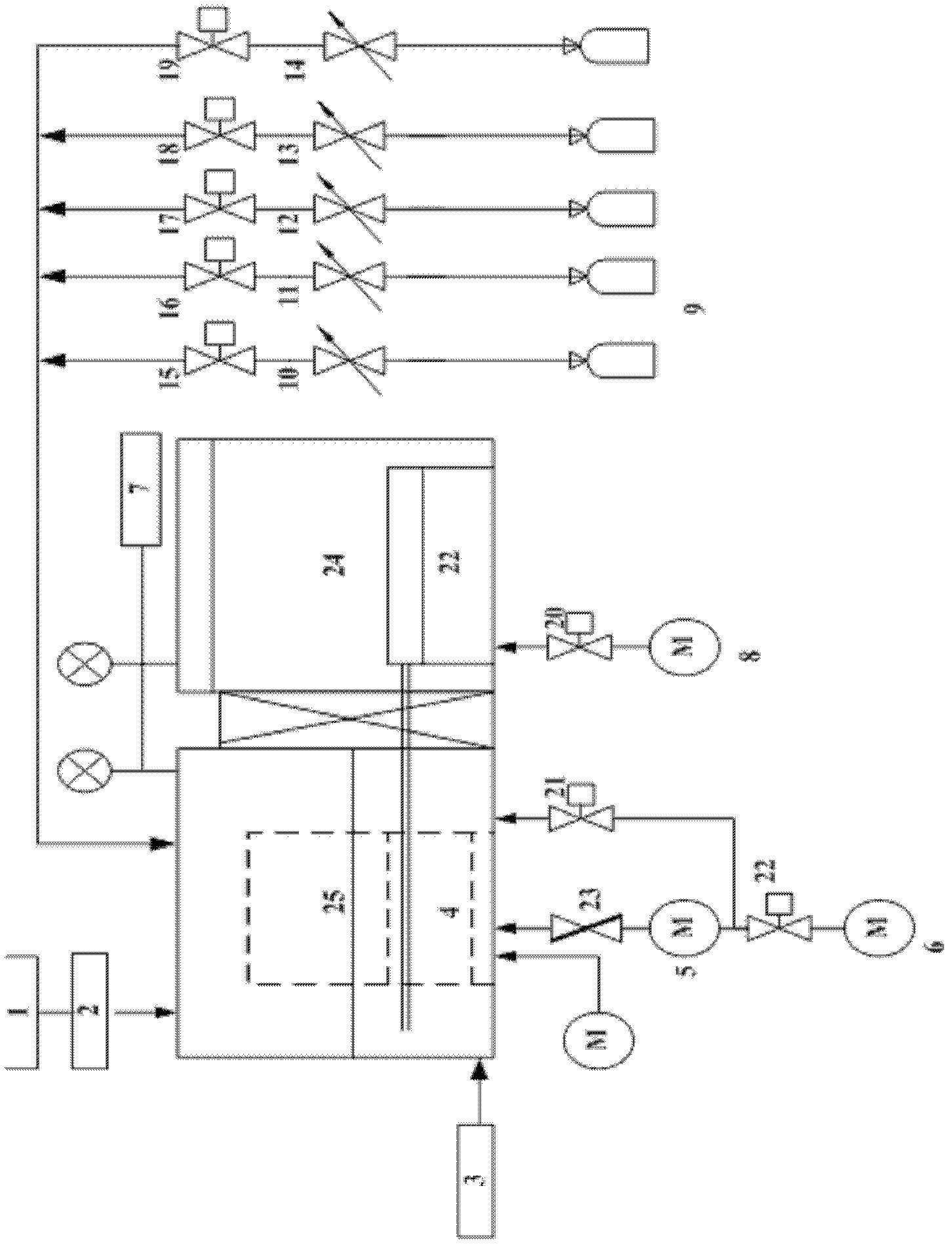
[0011] see figure 1 , an ion implanter provided by an embodiment of the present invention includes a vacuum system, a sheet feeding system, a gas feeding system, and a power supply system.

[0012] Wherein, the radio frequency power supply system includes a radio frequency power supply 1 , a radio frequency power supply matcher 2 and a pulse power supply 3 . The RF power supply 1 provides the energy required by the plasma for the reaction. The pulse power supply 3 provides a plasma implantation environment for the reaction.

[0013] The vacuum system includes a pre-pumping chamber 24 and a reaction chamber 25 . The reaction chamber 25 is connected with the pre-pumping chamber 24 by a gate valve. Wherein, the pre-pumping chamber 24 is a space for placing and transporting silicon wafers, its pressure can be changed between atmospheric pressure and low vacuum, and the vacuum can be obtained by a mechanical pump. The reaction chamber 25 requires a higher vacuum environment, wh...


PUM


Abstract

The invention discloses an ion implanter which comprises a power supply system, a reaction cavity, a pre-pumping cavity, a vacuum control system, a slice sending system and an air sending system. The vacuum control system is respectively connected with the reaction cavity and the pre-pumping cavity. The reaction cavity is connected with the pre-pumping cavity. The slice sending system is used for sending silicon slices to the reaction cavity from the pre-pumping cavity and sending the silicon slices to an ion reaction position in the reaction cavity. The air sending system is used for keeping reaction and sweeping gas into the reaction cavity. An injection mode of a traditional ion implanter is abandoned, complicated structures such as quality analysis, ion beam focusing, a scanning system and the like are eliminated, and the ion implanter which has simple structure and can be used for large area injection is provided.

Description

technical field [0001] The invention relates to the technical field of plasma implantation, in particular to an ion implanter. Background technique [0002] The ion implanter currently used in the field of IC manufacturing generally consists of an ion source system, an ion extraction and acceleration system, a mass analysis system, an ion beam focusing and scanning system, a target chamber system and a vacuum system. This type of ion implanter has the advantages of high purity of implanted ions and precise control of implant dose, but there are also some shortcomings: 1. The principle and structure are relatively complicated, and the purchase and maintenance are expensive; 2. The size of the substrate is too small to Large-area injection; 3. The temperature required for activation after injection is relatively high. Compared with IC manufacturing, although there are similarities in the process, the newly developed large-area implantation process puts forward new requirement...

Claims


Application Information

Patent Timeline
Patent Type & Authority Applications(China)
IPC IPC(8): H01L21/265
Inventor 王蒙李勇滔赵章琰李超波夏洋
Owner INST OF MICROELECTRONICS CHINESE ACAD OF SCI
Features
  • R&D
  • Intellectual Property
  • Life Sciences
  • Materials
  • Tech Scout
  • Unparalleled Data Quality
  • Higher Quality Content
  • 60% Fewer Hallucinations
Learn More