Vehicle power transmission control device

A technology of power transmission and control device, which can be used in power devices, control devices, pneumatic power devices, etc., and can solve problems such as power consumption

Inactive Publication Date: 2013-06-05
AISIN AI CO LTD +1
View PDF5 Cites 16 Cited by
  • Summary
  • Abstract
  • Description
  • Claims
  • Application Information

AI Technical Summary

Problems solved by technology

[0012] As described above, when an upshift operation is performed while being assisted by the mot

Method used


Image

  • Vehicle power transmission control device
  • Vehicle power transmission control device
  • Vehicle power transmission control device

Examples


Embodiment Construction

[0028] Embodiments of the power transmission control device for a vehicle according to the present invention will be described below with reference to the drawings.

[0029] (structure)

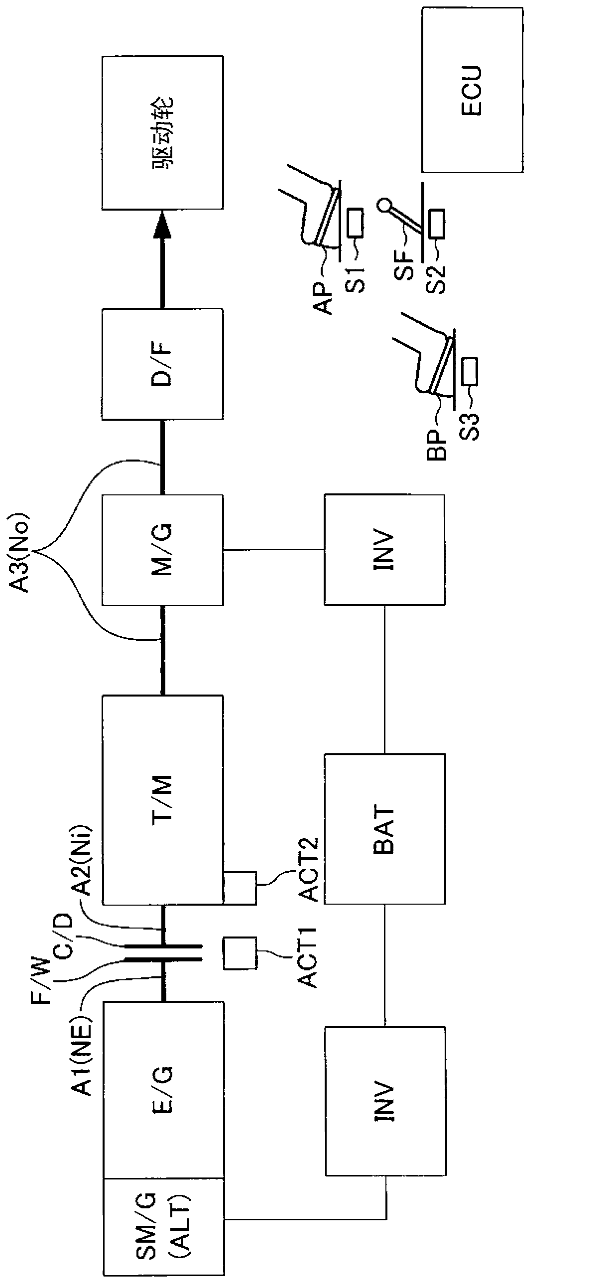
[0030] figure 1 A schematic configuration of a vehicle equipped with a power transmission control device (hereinafter referred to as "this device") according to an embodiment of the present invention is shown. This vehicle is a hybrid vehicle having an internal combustion engine and a motor generator as power sources and having a so-called electromechanical automatic transmission (AMT) using an active stage transmission and clutch.

[0031] This vehicle has an engine E / G, a transmission T / M, a clutch C / D, and a motor generator M / G. The E / G is one of known internal combustion engines, for example, a gasoline engine that uses gasoline as fuel, and a diesel engine that uses light oil as fuel.

[0032]An output shaft A1 of the engine E / G is configured to be driven and rotated by a starter mot...


PUM


Abstract

A state in which a vehicle travels while an internal combustion engine drive torque (Te) is transmitted to a driving wheel wherein, Te and a clutch torque Tc are reduced and an electric motor torque (Tm) is increased based on the fact that a shift up condition has been established (t1). Thereafter, based on the fact that Tc is zero (t2), Tc is maintained at zero, and while maintaining a state in which Tm is transmitted to the driving wheel, a shift up operation is performed (t2 - t3). Then, based on the fact that the shift up operation is complete (t3), Te and Tc are increased and Tm is reduced (T3 - T5). After the shift up condition has been established, during the time until Tc becomes zero, the load torque (Ts) of a generator rotatably driven by the power shaft of the internal combustion engine is generated. In a hybrid vehicle equipped with an AMT, the power consumption accorded to the electric motor drive when shifting up while using the assist for the electric motor torque can be reduced.

Description

technical field [0001] The present invention relates to a power transmission control device for a vehicle, and particularly relates to a power transmission control device for a vehicle that is applicable to a vehicle having an internal combustion engine and an electric motor as power sources and a clutch. Background technique [0002] In recent years, a power transmission control device has been developed (for example, refer to Patent Document 1), which has: a stepped transmission having a plurality of shift speeds and not having a torque converter; a clutch inserted in the Between the output shaft of the internal combustion engine and the input shaft of the stepped transmission and can adjust the clutch torque (the maximum value of the torque that the clutch can transmit); the control mechanism that uses the actuator to control the clutch torque and The gears of the stepped transmission. This power transmission control device is also called an electromechanical automatic t...

Claims


Application Information

Patent Timeline
IPC IPC(8): B60K6/442B60K6/547B60L11/14B60W10/02B60W10/06B60W10/08B60W10/11B60W30/19F02D29/02F16H63/50B60L50/16
CPCB60L2240/507Y02T10/642Y02T10/6234B60W20/30B60K6/547Y02T10/7241B60K6/442F16H2061/0433Y02T10/70B60L2220/14B60L2210/40Y02T10/7077B60L2250/26B60L2270/145B60L2240/443B60L11/14Y02T10/6286B60L2240/423F16H61/04B60W30/19B60W10/06B60W10/11F02D29/02B60L11/123Y02T10/6217B60W10/08B60W20/00B60W10/02B60L2250/24F16H63/502B60L50/61B60L50/16Y02T10/62Y02T10/64Y02T10/72Y02T10/7072B60W2710/083B60W2510/0275
Inventor 小林和贵中村祐一郎
Owner AISIN AI CO LTD
Why Eureka
Try Eureka