Automobile hydraulic braking device

A hydraulic brake and automobile technology, applied in the direction of hydraulic brake transmission device, brake actuator, gear transmission mechanism, etc., can solve problems such as malfunction, car slipping accident, loss of braking function, etc., and achieve high safety and reliability performance, ensuring safety and reliability, and reducing driving risks

Inactive Publication Date: 2013-06-12
高平市泫氏铸管有限公司
View PDF7 Cites 8 Cited by
  • Summary
  • Abstract
  • Description
  • Claims
  • Application Information

AI Technical Summary

Problems solved by technology

However, in case of abnormal conditions, the brake may fail and cause an accident.
When the car running downhill turns off abnormally or the driver misuses the engine, the brake hydraulic pump stops working because the engine stops, there is no pressure oil output, and the brake pads and brake discs cannot move relative to each other. The braking function is lost due to frictional resistance, and the car will accelerate infinitely due to inertia. At this time, it will cause an accident due to the inability to brake.
When the brake hydraulic pump, brake cylinder, valves, and pipelines are damaged or leaked during driving, the brake oil pressure cannot be maintained or completely lost pressure, which will also cause brake delay or failure, especially when driving at high speed. When emergency braking is performed, it is likely to cause a serious accident
In the case of parking on a slope, if the engine is turned off, if the driver forgets to tighten the parking brake, even in the case of shifting gears, because the brake pump stops running and there is no pressure oil output, the service brake is invalid at this time, and a rolling accident may occur

Method used


Image

  • Automobile hydraulic braking device
  • Automobile hydraulic braking device
  • Automobile hydraulic braking device

Examples


Embodiment Construction

[0019] The present invention will be further described below in conjunction with the accompanying drawings.

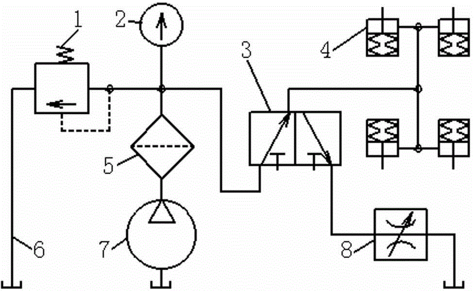
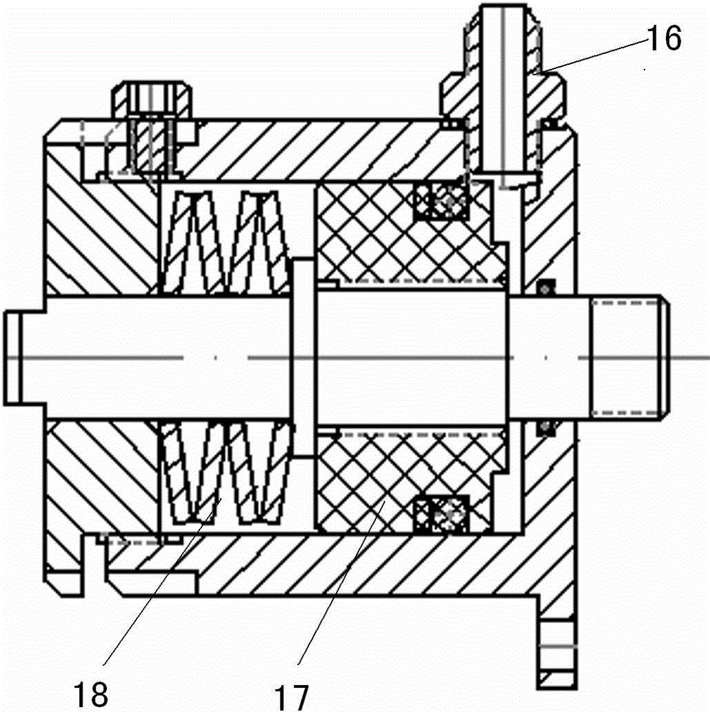
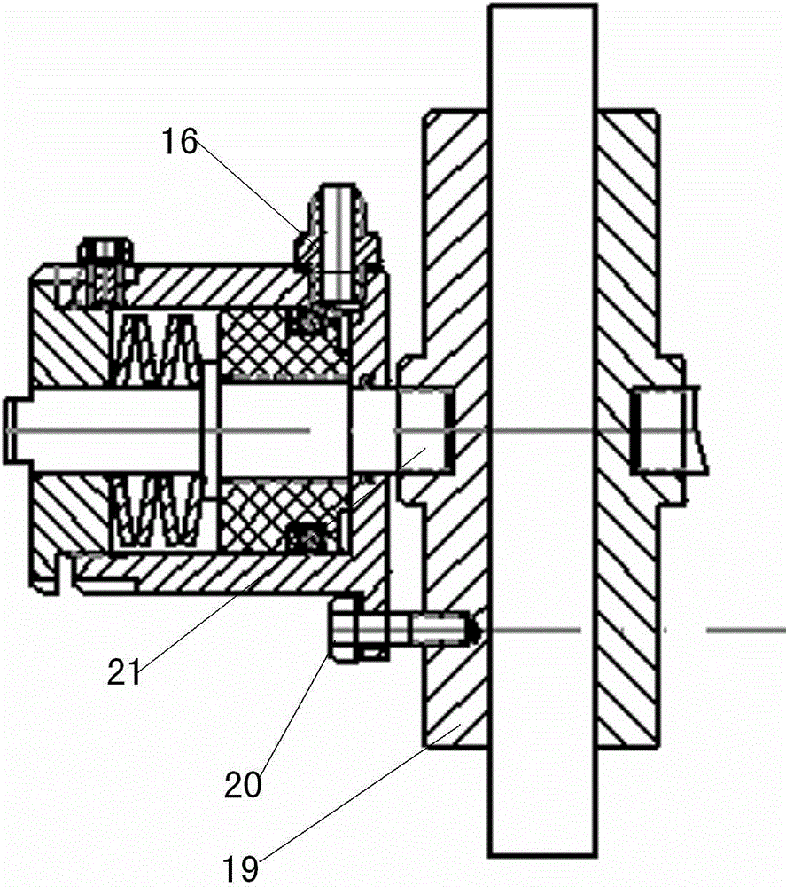
[0020] Such as figure 1 , 3 A kind of automobile hydraulic braking device shown in , 5, comprises oil pump 7, filter 5, pressure gauge 2, control valve 3, brake oil cylinder 4, adjustable throttle valve 8, overflow valve 1, oil return pipe 6; One side of the valve body 13 of the control valve 3 is provided with an oil inlet 9 and an oil return port 10, and the other side is provided with an oil outlet 11, and a spring 14 is provided between the end of the valve core 12 and the valve body 13, and the valve core 12 is provided with a valve hole 15, when the spool 15 moves, the oil outlet 11 communicates with the oil inlet 9 or the oil return port 10 through the valve hole 15; the cylinder oil inlet of the brake cylinder 4 is provided with an oil pipe A butterfly spring 18 is arranged between the joint 16, the end of the piston 17 and the cylinder body, the brake bl...


PUM


Abstract

The invention discloses an automobile hydraulic braking device, which comprises an oil pump, a filter, a pressure gauge, a control valve, a braking oil cylinder, an adjustable flow valve, an overflow valve and an oil return pipe, wherein an oil inlet and an oil return port are formed in one side of the valve body of the control valve, and an oil outlet is formed in the other side of the valve body of the control valve; a spring is arranged between the tail end of the valve core and the valve body; the valve core is provided with a valve hole; when the valve core moves, the oil outlet is communicated with the oil inlet or the oil return port through a valve hole; a cylinder body oil inlet of a braking oil cylinder is provided with an oil pipe joint; a belleville spring is arranged between the tail end of a piston and the cylinder body; a brake block is fixed to the cylinder body through a stop screw; the tail end of a piston rod is then connected with the brake block through a connecting screw; the oil pump is connected with the filter; the filter is communicated with the oil inlets of the overflow valve and the control valve through an oil path provided with the pressure gauge respectively; the oil outlet of the control valve is communicated with an oil pipe joint of the braking oil cylinder; the oil return port is communicated with the adjustable flow valve; and the overflow valve is connected with the oil return pipe. The automobile hydraulic braking device has extremely high safety and reliability, and the driving risk can be effectively reduced.

Description

technical field [0001] The invention belongs to the field of automobile manufacturing, and relates to an automobile brake system, in particular to an automobile hydraulic brake device. Background technique [0002] The car that uses now, braking device is generally tight brake brake. The basic principle is that when the car is running normally, there is a certain gap between the brake pad and the brake disc. When decelerating, stopping or emergency parking in case of an accident, the driver needs to step on the brake pedal to operate the brake system. , Through the pressure oil entering the piston chamber of the brake cylinder, the plunger and the brake pads are pushed to apply a horizontal extrusion force to the brake disc at the same time, and the frictional resistance forces the speed of the brake disc to reduce, stop, achieve deceleration or stop. [0003] Under normal circumstances, as long as the engine and the brake hydraulic system can work normally, the braking per...

Claims


Application Information

Patent Timeline
Patent Type & Authority Applications(China)
IPC IPC(8): B60T11/10F16D65/14F16D121/04
Inventor 牛国亮
Owner 高平市泫氏铸管有限公司
Why Eureka
Try Eureka