Double intake high-pressure large flow rate cement kiln centrifugal fan

A technology of centrifugal fan and large flow, which is applied in the direction of mechanical equipment, machine/engine, liquid fuel engine, etc., to achieve the effect of material saving, cost reduction and weight reduction

Inactive Publication Date: 2013-06-12
贵阳远大风机制造有限公司
View PDF6 Cites 6 Cited by
  • Summary
  • Abstract
  • Description
  • Claims
  • Application Information

AI Technical Summary

Problems solved by technology

[0003] The current fan can no longer meet the status quo. Therefore, it is necessary to re-introduce a fan with higher pressure, larger air volume adjustment range and higher efficiency to meet the existing production requirements.

Method used


Image

  • Double intake high-pressure large flow rate cement kiln centrifugal fan
  • Double intake high-pressure large flow rate cement kiln centrifugal fan
  • Double intake high-pressure large flow rate cement kiln centrifugal fan

Examples


Embodiment Construction

[0020] The present invention will be described in further detail below in conjunction with specific embodiments and accompanying drawings.

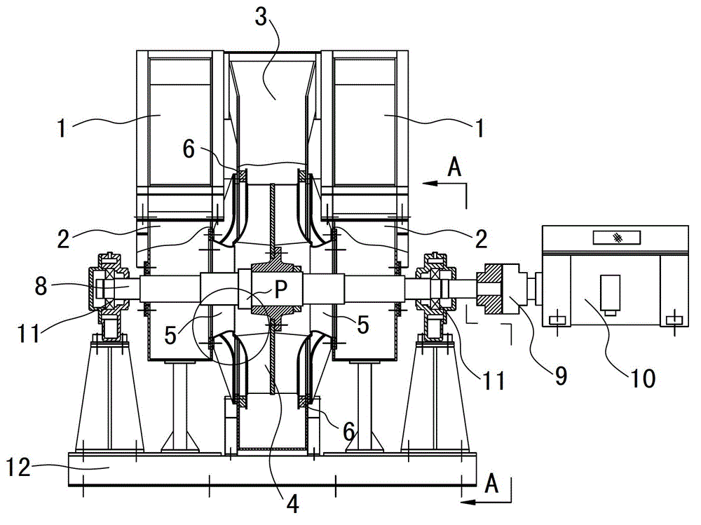
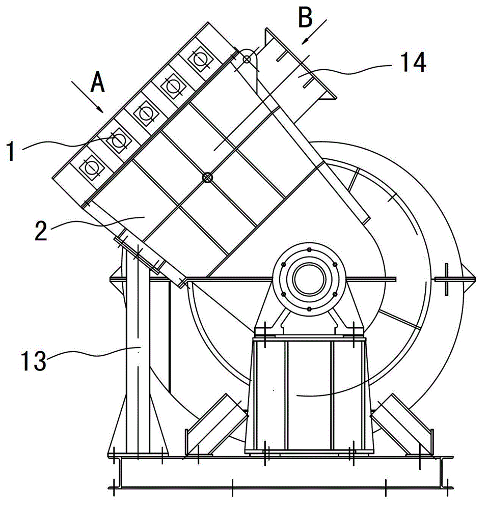
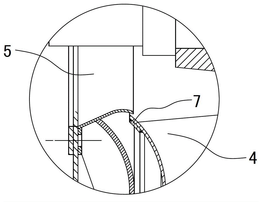
[0021] a kind of like Figure 1-3 The shown double-inlet high-pressure and large-flow centrifugal fan for cement shaft kiln includes a centrifuge casing 3 and an impeller group 4 therein. The impeller group 4 is positioned in the centrifuge casing 3 through the rotation of the main shaft 8. The casing 3 is connected with two opposite air inlet groups 5, the two air inlet groups 5 are concentric with the main shaft 8, and communicate with the inside of the centrifuge casing 3; the impeller group 4 is fixed The impeller disc on the main shaft 8 and two groups of impellers respectively fixed on the two sides of the impeller disc are composed. The centers of the two groups of impellers correspond to the two air inlet groups 5 respectively. A reinforcing ring 7 is arranged at the place, and a diffuser guide ring 6 is respectively arranged on ...


PUM


Abstract

The invention discloses a centrifugal fan, particularly discloses a double intake high-pressure large flow rate cement kiln centrifugal fan, which comprises a centrifugal fan casing and a blade group in the centrifugal fan casing, the blade group is positioned in the centrifugal fan casing via a main shaft in a rotating manner; two air intake groups are connected to the centrifugal fan casing in a back-to-back manner; the two air intake groups take the same central axis with the main shaft, and are communicated with the interior of the centrifugal fan casing; the blade group is formed by a blade disc fixedly arranged on the main shaft and two groups of blades respectively fixed on the two side surfaces of the blade disc, the centers of the two groups of blades correspond to the two air inlet groups, reinforcing rings are arranged at the two front disc inlets of the blade groups, pressure expansion guide rings are respectively arranged on the two inner walls of the centrifugal fan in positions close to the blade air outlet end part, and the pressure expansion guide rings do not collide with the impeller. The centrifugal fan is flat in performance curve, large in flow capacity regulation range and high in efficiency.

Description

technical field [0001] The invention relates to a centrifugal fan, in particular to a centrifugal fan for a cement shaft kiln with double air inlets, high pressure and large flow. Background technique [0002] In the current cement shaft kiln ventilation field, the air volume of the generally used centrifugal fan is basically 30000m 3 / h, the flow adjustment range is small, the efficiency is low, and the average efficiency is only about 75%. The main transport medium is non-corrosive, non-spontaneous, and non-viscous gas. The temperature of the medium generally does not exceed 80°C, and the dust content is low. More than 150mg / m 3 , It can also be used for various ventilation in petrochemical, building materials, metallurgy, electric power and material transportation. However, with the increase of the output of the production line in the cement industry, fans with high pressure and larger air volume are needed to meet the requirements of the shaft kiln production line. ...

Claims


Application Information

Patent Timeline
Patent Type & Authority Applications(China)
IPC IPC(8): F04D29/42F04D29/28F04D29/053
Inventor 杨琼
Owner 贵阳远大风机制造有限公司
Why Eureka
Try Eureka