
Spectrum detection method and device for dielectric barrier discharge

A technology of dielectric barrier discharge and detection method, applied in the field of instrument analysis, can solve the problems of low plasma temperature, low sensitivity, large gas consumption, etc., and achieve the effects of simple detection part, improved sensitivity and less gas consumption

Inactive Publication Date: 2013-06-12
HOHAI UNIV
View PDF8 Cites 6 Cited by
  • Summary
  • Abstract
  • Description
  • Claims
  • Application Information

AI Technical Summary

Problems solved by technology

[0003] At present, the disclosed methods for dielectric barrier discharge detection all lead the generated plasma out of the generator for detection, and must have a shielding gas. Due to the low temperature and small volume of the plasma generated by dielectric barrier discharge, it makes the Short optical path, instability, low sensitivity, large gas consumption and complex structure, etc.

Method used


Image

  • Spectrum detection method and device for dielectric barrier discharge
  • Spectrum detection method and device for dielectric barrier discharge

Examples


Embodiment 1

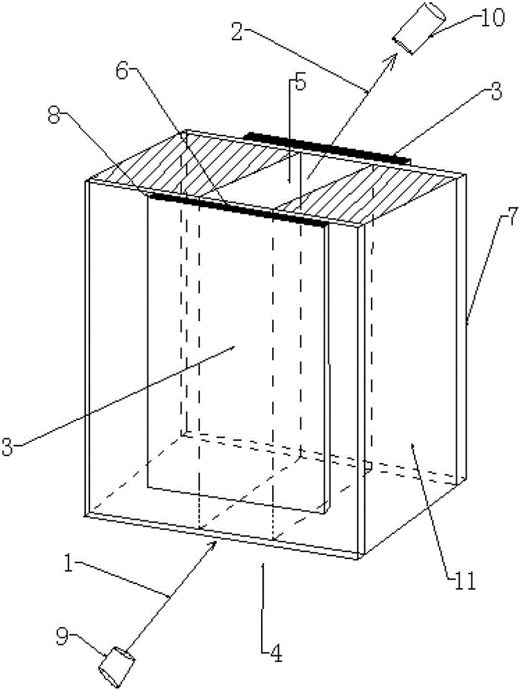
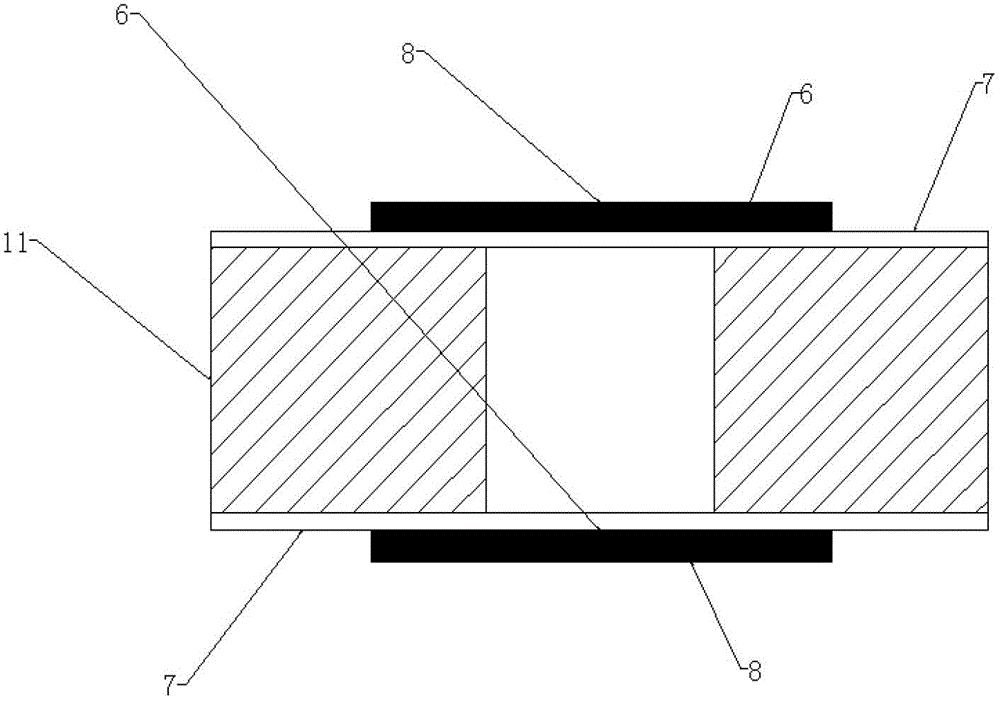
[0027] Example 1: The dielectric barrier discharge device is composed of 2mm glass 11 and 1mm quartz 7 in a cavity of 2mm×6mm×60mm, the distance between the barrier media is 2mm, the outside of quartz 7 is pasted with copper electrode plate 8, and the outside of quartz 7 is silver plated. The silver-plated layer 6 and the quartz 7 form a mirror, and the copper electrode plate 8 is connected to a high-voltage high-frequency power supply through a wire 3, and the voltage is 2000V and the frequency is 30KHZ.

[0028] The standard solution Hg is formed into a hydride, the carrier gas is blown off to form Hg vapor, and the Hg vapor enters the discharge chamber from the carrier gas inlet 4. The helium gas is introduced into the discharge chamber at 300ml / mim, and the high-voltage and high-frequency power supply is turned on to form plasma The carrier gas outlet 5 is discharged, and the illuminator 9 hollow cathode lamp produces incident light 1 from the carrier gas inlet 4 at an angle o...

Embodiment 2

[0031] Example 2: The cavity is composed of 4mm quartz 11 and 1.5mm heat-resistant glass 7 to form a 4mm×5mm×70mm cavity. The distance between the barrier media is 4mm. An aluminum plate 8 is attached to the outside of the heat-resistant glass 7, the surface of the aluminum plate 6 and the barrier The two smooth sides of the medium are combined into a mirror (such as figure 2 As shown), the aluminum electrode plate 8 is connected to a high-voltage and high-frequency power supply through a wire 3, and the voltage is 7000V and the frequency is 3MHZ.

[0032] The standard solution Cr solution is sprayed pneumatically to make the Cr solution form vapor, the vapor enters the discharge chamber from the carrier gas inlet 4, and the nitrogen is introduced into the discharge chamber at a flow rate of 200ml / mim, and the high-voltage and high-frequency power supply is turned on to form plasma and emit light at the same time The laser light in the device 9 produces incident light 1 from the ...


PUM

PropertyMeasurementUnit
thicknessaaaaaaaaaa

Abstract

The invention provides a spectrum detection method and a spectrum detection device for dielectric barrier discharge. The detection method comprises the following steps that after the dielectric barrier discharge generates plasma, the incident light enters from an inclined angle, is repeatedly reflected in a reflection layer in a dielectric barrier discharge cavity and is emitted from the carrier gas outlet at the inclined angle, the emitted light is received by the detector, and the signal is detected. The light path length can be adjusted by adjusting the incident angle according to the needs, and because the incident light is emitted in an angle, the backlight light interference generated by discharge is effectively avoided. Compared with the conventional detection method, the method has the advantages that the sensitivity and stability are effectively improved, the method is simple in structure, small in size and low in gas consumption, and miniaturization of the instrument is easily realized.

Description

technical field [0001] The invention relates to a spectral detection method and device for dielectric barrier discharge, belonging to the technical field of instrument analysis. Background technique [0002] The structural characteristic of dielectric barrier discharge is that there is at least one layer of insulating barrier medium and small discharge channels. When a sufficiently high AC voltage is applied to the discharge electrodes, the gas between the electrodes, even under atmospheric pressure, will be broken down to form a dielectric barrier discharge. The discharge has the advantages of being realized under atmospheric pressure, small volume, low energy consumption, and low gas temperature. The discharge phenomenon is blue-purple, uniform, loose and stable, and is actually composed of a large number of tiny fast pulse discharge channels. It has broad application prospects in atomic fluorescence, atomic emission, and atomic absorption analysis methods. [0003] At ...

Claims


Application Information

Patent Timeline
Patent Type & Authority Applications(China)
IPC IPC(8): G01N21/67
Inventor 洪陵成张欢
Owner HOHAI UNIV
Learn More