Gap flowing status maintaining device

A fluid dynamic and gap technology, applied in microscopes, optics, instruments, etc., can solve the problems of destroying the uniformity of the liquid in the observation area, deteriorating the observation quality, reducing the work efficiency, etc., and achieving high-quality long-term observation capability and long-term continuous reliable observation , the effect of improving the quality of observation

Inactive Publication Date: 2014-12-03
FUZHOU UNIV
View PDF7 Cites 0 Cited by
  • Summary
  • Abstract
  • Description
  • Claims
  • Application Information

AI Technical Summary

Problems solved by technology

However, there is often a certain degree of pollution on the surface of the base to be observed and its periphery. With the continuous observation of different positions, the liquid is easily contaminated. If backflow occurs, the uniformity of the liquid in the observation area will be destroyed and the observation quality will be deteriorated.
[0007] 2) Backflow caused by substrate movement can easily lead to contamination deposition, resulting in continuous observation distortion
After reflow, the pollutants are closer to the lower surface of the objective lens, and are more likely to be adsorbed on the surface of the objective lens, which will cause long-term damage
Adding an objective lens cleaning process after observation (for example, see Japanese patent JP2007065257A) will help to obtain a clean objective lens surface, but it will reduce work efficiency and indirectly increase the cost of observation

Method used


Image

  • Gap flowing status maintaining device
  • Gap flowing status maintaining device
  • Gap flowing status maintaining device

Examples


Embodiment Construction

[0038] The specific implementation of the present invention will be described below in conjunction with the drawings and examples.

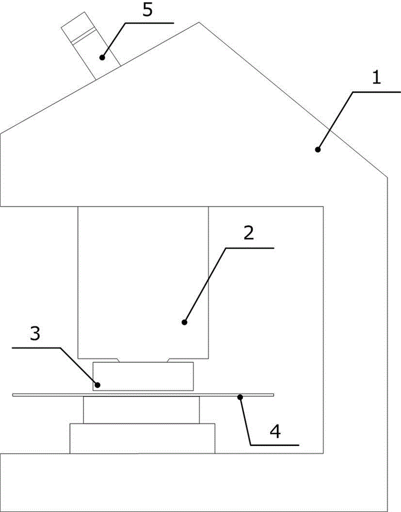
[0039] figure 1 Schematically shows the assembly of the slit flow dynamic maintenance device and the lens group of the embodiment of the present invention, the slit flow dynamic maintenance device 3 arranged between the lens group 2 and the substrate 4 can be used in microscopic equipment such as an immersion microscope 1 application. In actual observation, the light on the surface of the substrate 4 (silicon wafer or liquid crystal substrate, etc.) is captured by related equipment for microscopic analysis through the slit liquid film above the substrate 4 (not shown in the figure) and the lens group 2. For the consideration of equipment utilization and economy, immersion microscopic observation can have two modes: direct visual inspection and image analysis. If the wavelength of the observation light is visible light, it can be directly observ...


PUM


Abstract

The invention discloses a gap flowing status maintaining device which is of a device arranged between a lens group and a substrate, an observation cavity is arranged at the center of the gap flowing status maintaining device, the gap flowing status maintaining device is outward provided with an injection and recovery discharge hole array, an injection cavity, a recovery cavity, an injection end absorbing liquid discharge hole and a recovery end supplementary liquid discharge hole in sequence. Through a liquid delivery scheme combining a liquid supply cavity and non-even discharge holes, a large-range unidirectional strong liquid flow is formed in the observation area, thereby effectively stopping the polluted liquid from entering the observation area. In addition, the polluted liquid moving along with the substrate is directly absorbed at the periphery of the observation area through arranging a liquid absorption and supplementary channel, thereby further ensuring the uniformity and stability of the liquid in the observation area and eliminating the secondary pollution of an objective lens, being capable of realizing long-term and continuous reliable observation, and especially being applicable to a microscope observation system needing the high-speed movement of the substrate.

Description

Technical field: [0001] The invention relates to a slit flow dynamic maintaining device in an immersion microscope system, in particular to a slit flow dynamic maintaining device for an immersion microscope (Immersion Microscope). Background technique: [0002] In industries such as semiconductors, fault analysis and reliability evaluation of tiny electronic devices are the key to ensuring yield. The usual way is to use the electronic device as a sample and observe it under a microscope to determine whether there are defects or impurities that affect the normal operation of the device. However, as the characteristic line width of electronic devices continues to shrink below 32 nanometers, and the size of substrates (such as semiconductor silicon wafers) continues to increase, the technical cost of traditional observation methods is rising rapidly. [0003] Immersion microscope system, by filling the thin layer gap between the front end of the objective lens and the substrat...

Claims


Application Information

Patent Timeline
Patent Type & Authority Patents(China)
IPC IPC(8): G02B21/33
Inventor 陈晖陈淑梅杜恒
Owner FUZHOU UNIV
Why Eureka
Try Eureka