Self-adaption method of zero compensation detection of rotary transformer of permanent magnet motor

A resolver and permanent magnet motor technology, which is applied in the control of generators, motor generators, electromechanical brakes, etc., can solve the problems of permanent magnet motor torque accuracy deviation, waste of manpower and material resources, and system control out of control, so as to improve the accuracy and system security, saving manpower and material resources

Active Publication Date: 2013-06-12
SHANGHAI DAJUN TECH
View PDF8 Cites 39 Cited by
  • Summary
  • Abstract
  • Description
  • Claims
  • Application Information

AI Technical Summary

Problems solved by technology

If the zero position of the magnetic field of the permanent magnet motor cannot be accurately detected, there will be obvious deviations in the output torque accuracy of the permanent magnet motor, and the peak power of the permanent magnet motor cannot be guaranteed. What is more serious will cause the system control to be out of control, resulting in a large number of problems in the system. big security risk
[0003] At present, the compensation for detecting the zero position of the resolver of the permanent magnet motor is usually obtained during the test process of the permanent magnet motor, which requires each permanent magnet motor to artificially recalibrate the zero position deviation detected by the resolver of the permanent magnet motor itself. Brings a lot of waste of manpower and material resources, and is not suitable for mass production of permanent magnet motors

Method used


Image

  • Self-adaption method of zero compensation detection of rotary transformer of permanent magnet motor
  • Self-adaption method of zero compensation detection of rotary transformer of permanent magnet motor

Examples


Embodiment Construction

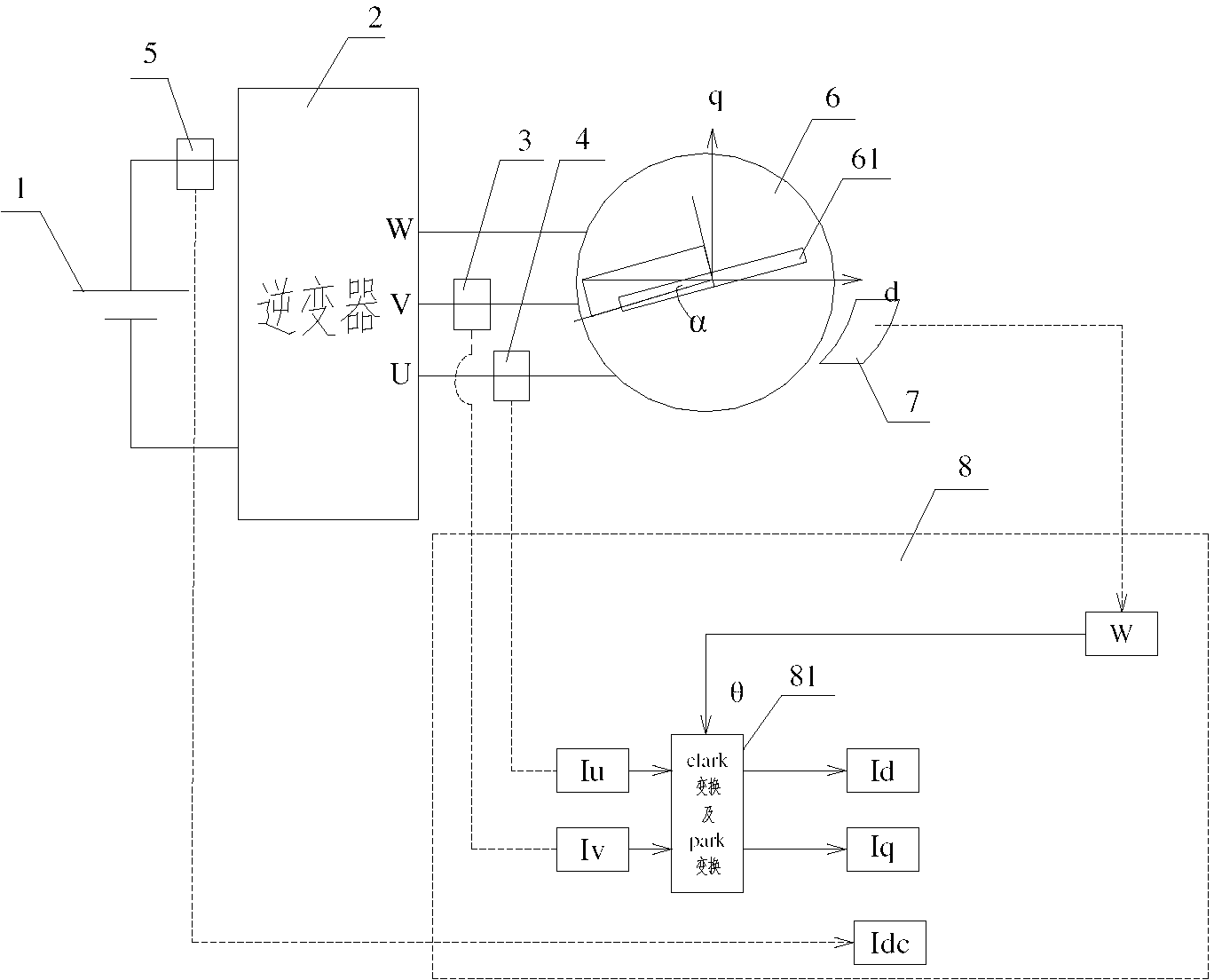
[0028] Such as figure 1 and figure 2 As shown, the self-adaptive method for detecting zero position compensation of the permanent magnet motor resolver of the present invention includes the following steps:

[0029] Step 1. The power module 1 drives the permanent magnet motor 6 to run through the inverter 2. The micro-control processor 8 detects the rotational speed, the direction of rotation and the position of the rotor 61 of the permanent magnet motor 6 through the resolver 7. The DC bus of the power module 1 is provided with a first The current sensor 5, the V phase and the U phase of the permanent magnet motor 6 are respectively provided with the second current sensor 3 and the third current sensor 4, and the preset CLARK transformation algorithm and the PARK transformation algorithm are preset in the software algorithm module 81 of the microcontroller processor 8;

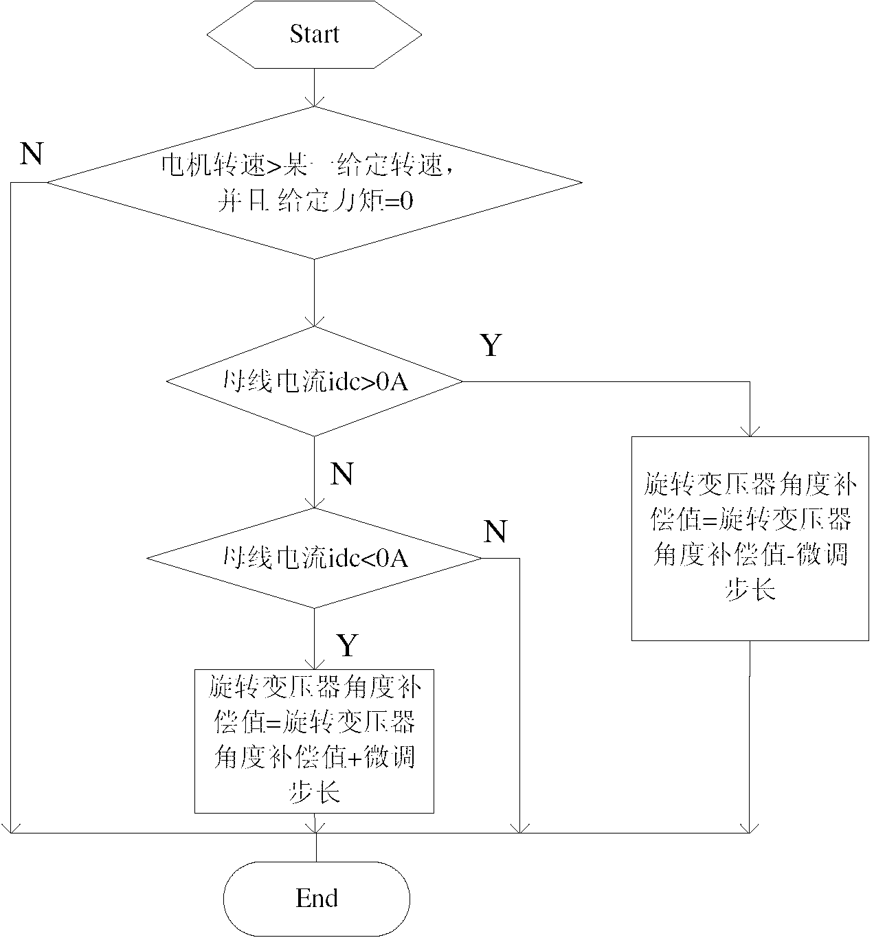
[0030] Step 2. During the operation of the permanent magnet motor 6, the current Idc of the DC bus of th...


PUM


Abstract

The invention discloses a self-adaption method of zero compensation detection of a rotary transformer of a permanent magnet motor. The rotary transformer detects the rotate speed, the direction of rotation and the rotor position of the permanent magnet motor; three current sensors respectively detect direct current bus current Idc, motor V-phase current Iv and motor U-phase current Iu, and rotor d shaft current Id and rotor q shaft current Iq are obtained by means of CLARK conversion and PARK conversion through a micro-programming controller; the permanent magnet motor is adjusted to be in a zero torque control mode, at the moment the Id equals to flux-weakening current and the Iq equals to zero; when a magnetic field of the permanent magnet motor is zero position alignment, the Idc is approximate to zero; in case that the zero position of the magnetic field deviates, the Idc is not approximate to zero; a rotary transformer deviation angle is regulated and rotated through the micro-programming controller until the Idc is approximate to zero and a rotor of the permanent magnet motor and a d shaft coincide. The self-adaption method can detect the accurate position of a motor rotor in real time, avoids a process of zero compensation manual calibration, improves torque control accuracy of a motor and system security, and is suitable for mass manufacturing of the motor.

Description

technical field [0001] The invention relates to an adaptive method for detecting zero position compensation of a rotary transformer of a permanent magnet motor. Background technique [0002] Permanent magnet motors are widely used in hybrid vehicles and industrial servo systems. For mass-produced permanent magnet motors, due to current processing technology issues and cost considerations, the resolver of each permanent magnet motor is used to detect the magnetic field zero of the permanent magnet motor. There is a certain deviation in the position, and the current development trend of permanent magnet motors is miniaturization and low cost, which makes the flux linkage of permanent magnet motors generally designed to be very large. The requirements for zero detection of the magnetic field of permanent magnet motors are very high. If the zero position of the magnetic field of the permanent magnet motor cannot be accurately detected, there will be obvious deviations in the ou...

Claims


Application Information

Patent Timeline
Patent Type & Authority Applications(China)
IPC IPC(8): H02P21/14H02P21/18
Inventor 赵洪涛季胜利徐性怡
Owner SHANGHAI DAJUN TECH
Why Eureka
Try Eureka