
LED (Light Emitting Diode) driving circuit and constant-current control circuit thereof

A constant current control circuit and LED drive technology, applied in energy-saving control technology, lamp circuit layout, electric light source, etc., can solve problems such as reducing practicability, and achieve the effect of cost saving, high constant current precision and good stability

Active Publication Date: 2013-06-12
HANGZHOU SILAN MICROELECTRONICS
View PDF5 Cites 36 Cited by
  • Summary
  • Abstract
  • Description
  • Claims
  • Application Information

AI Technical Summary

Problems solved by technology

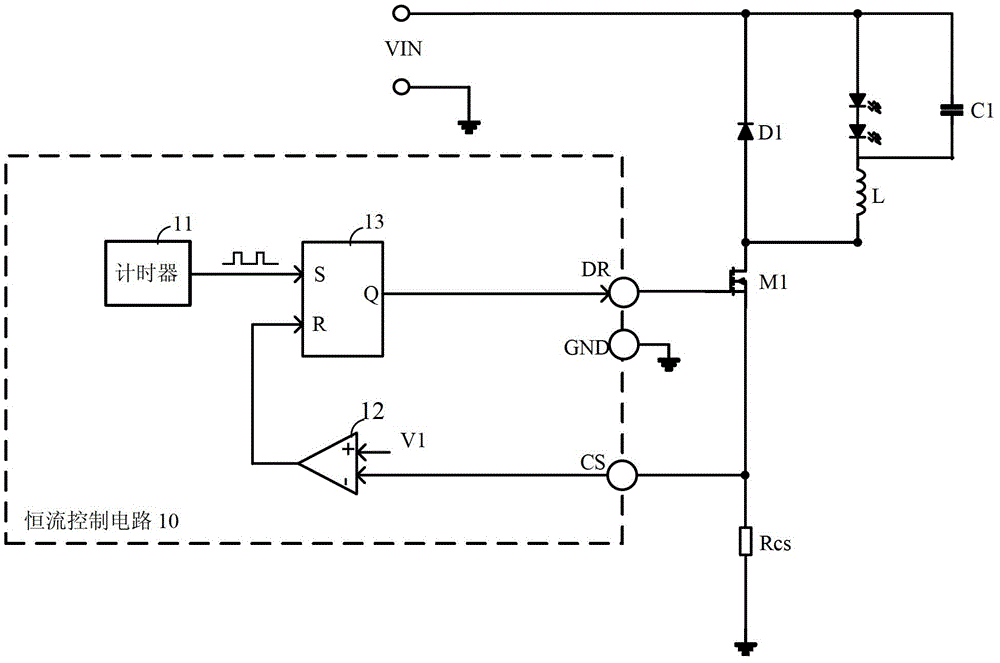
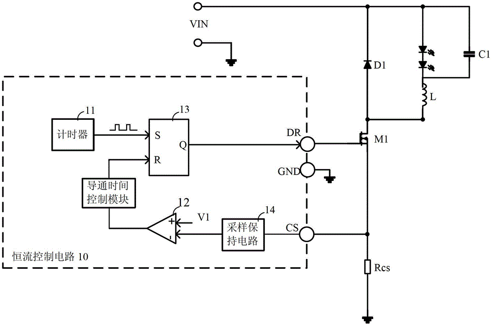
[0006] In the above-mentioned traditional drive circuit, there are the following disadvantages: the drive circuit controls the peak current and ripple current to keep the output current constant, and the peak current is determined by the comparison module 12, the reference voltage V1 and the sampling resistor Rcs
However, using Figure 4 The drive circuit shown will lead to an additional port for the constant current control circuit, which means an additional pin for the chip, which reduces the practicability

Method used


Image

  • LED (Light Emitting Diode) driving circuit and constant-current control circuit thereof
  • LED (Light Emitting Diode) driving circuit and constant-current control circuit thereof
  • LED (Light Emitting Diode) driving circuit and constant-current control circuit thereof

Examples


Embodiment Construction

[0074] The present invention will be further described below in conjunction with specific embodiments and accompanying drawings, but the protection scope of the present invention should not be limited thereby.

[0075] refer to Figure 5 , in the first embodiment of the present invention, the LED drive circuit includes: a constant current control circuit 30, a switch tube M1, a current limiting sampling resistor RILIM, a constant current sampling resistor Rcs, an inductor L, a freewheeling diode D1, an output capacitor C1, The first zero-crossing detection resistor R1 , the second zero-crossing detection resistor R2 , and the rectifier bridge 38 . The constant current control circuit 30 has a zero-crossing detection port ZCD, a drive port DR, a current limiting port ILIM, a sampling port CS, a ground port GND, and a compensation port COMP. The constant current control circuit 30 includes the following modules: an inductor current zero-crossing detection module 31 , an error a...


PUM


Abstract

The invention provides an LED (Light Emitting Diode) driving circuit and a constant-current control circuit thereof. The constant-current control circuit comprises an error amplifier, a turn-on time control module and a driving signal generation module, wherein the first input end of the error amplifier receives load current through a sampling port and the second input end of the error amplifier receives preset first reference voltage; the input end of the turn-on time control module is connected with the output end of the error amplifier; and the driving signal generation module generates a driving signal for turning off a switching tube in the LED driving circuit according to the output signal of the turn-on time control module, the driving signal is output through a driving port, a ground port is configured to receive floating ground voltage and the floating ground voltage is different from the reference ground voltage of the input voltage of the LED driving circuit. The constant-current control circuit has the advantages that the precise constant-current control can be realized, the power coefficient is high, the input harmonic is low, the working safety is high and the conversion efficiency is high.

Description

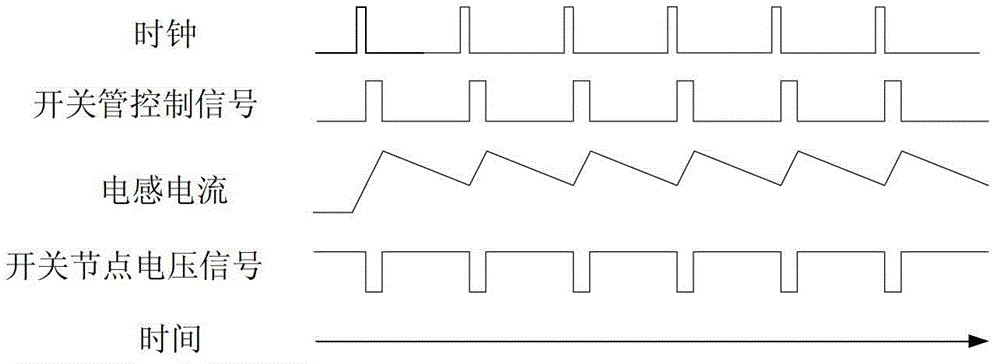
technical field [0001] The invention relates to LED drive technology, in particular to a high constant current precision LED drive circuit and a constant current control circuit thereof. Background technique [0002] At present, in the LED driving circuit, it can be divided into isolation mode and non-isolation mode according to the topology of the peripheral circuit, and divided into buck mode and boost-buck mode according to the level of input / output voltage. Because the hysteresis control is commonly used, the biggest disadvantage of the current non-isolated LED drive circuit is that the constant current characteristic is poor, and the output current is greatly affected by the change of the input voltage, output voltage and inductance. [0003] figure 1 It is a schematic diagram of an LED drive circuit working in a traditional step-down mode, mainly including a constant current control circuit 10, a freewheeling diode D1, an inductor L, a capacitor C1, a switch tube M1, ...

Claims


Application Information

Patent Timeline
IPC IPC(8): H05B37/02
CPCY02B20/40
Inventor 姚丰王栋
Owner HANGZHOU SILAN MICROELECTRONICS
Learn More