
Blood vessel interventional operation conduit or guide wire control device based on two-point clamping

A technology for manipulating devices and interventional surgery, applied in the direction of catheters, surgical robots, etc., can solve the problems of continuous advancement of catheters, thick catheters, narrow medical application range, etc., to overcome the loss of manipulation accuracy, increase the upper limit of friction, and improve the reliability manipulative effect

Active Publication Date: 2013-06-19
北京中科鸿泰医疗科技有限公司
View PDF5 Cites 52 Cited by
  • Summary
  • Abstract
  • Description
  • Claims
  • Application Information

AI Technical Summary

Problems solved by technology

[0004] In response to the above problems, Germany Hansen Medical (hansen meidical) modified the catheter structure and developed an active catheter system. The problem is that the modified catheter is thicker and the scope of medical application is narrower; Beihang University has made a pusher mechanism, but It is inconvenient to install, disassemble and disinfect the catheter; the Institute of Automation of the Chinese Academy of Sciences has designed a push tube device by simulating human hands, but it cannot continuously advance the catheter, and cannot complete the simultaneous movement of propulsion and rotation

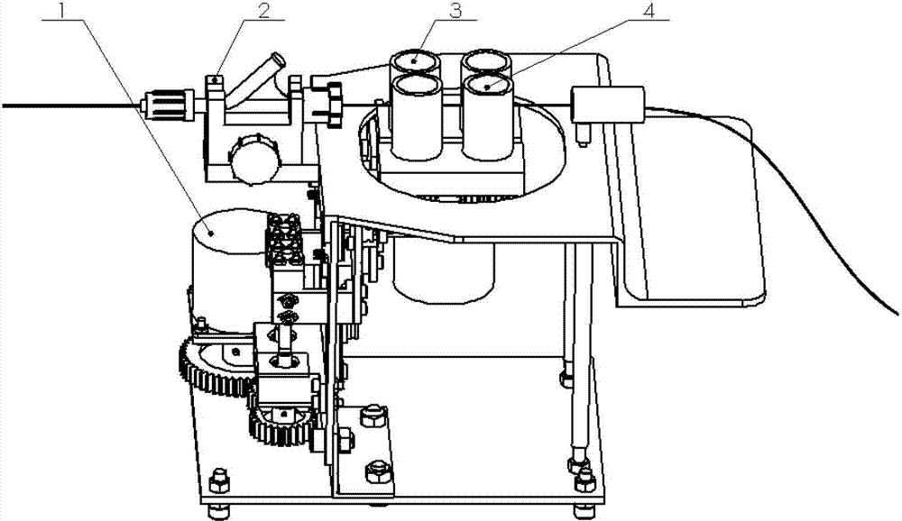
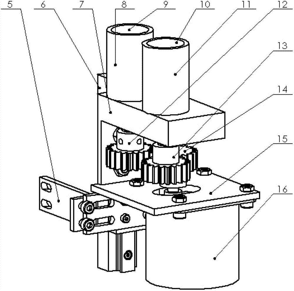
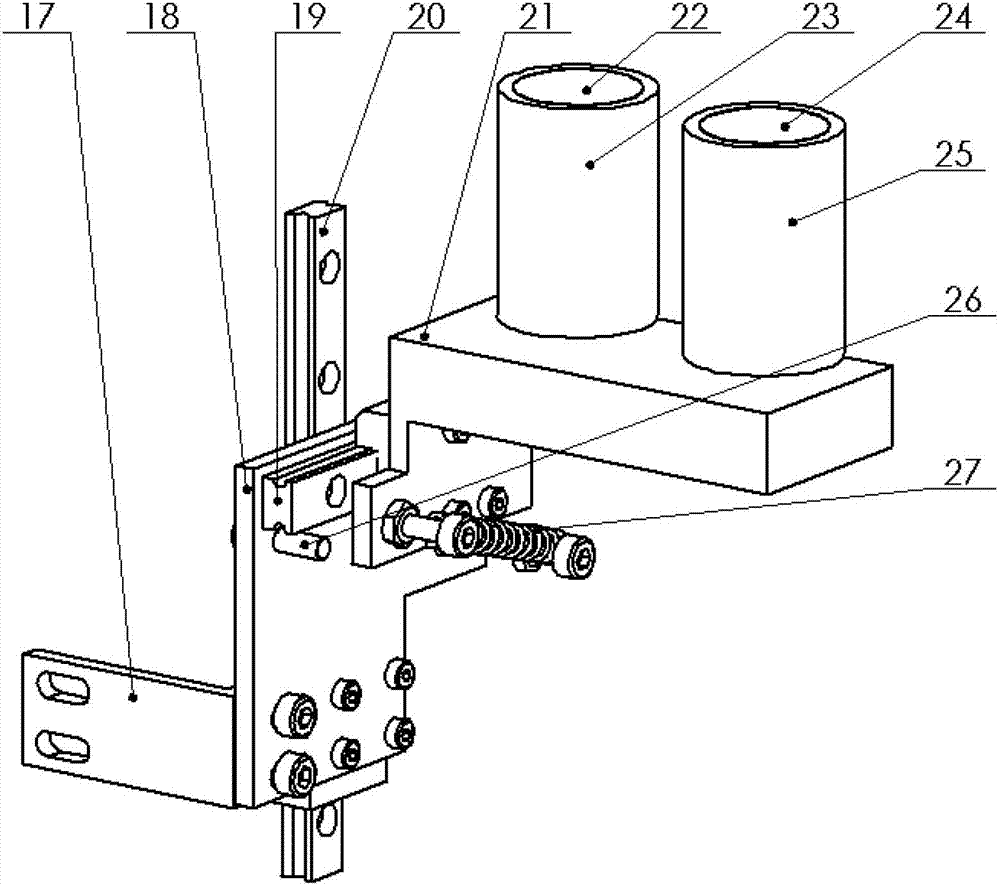
Method used


Image

  • Blood vessel interventional operation conduit or guide wire control device based on two-point clamping
  • Blood vessel interventional operation conduit or guide wire control device based on two-point clamping
  • Blood vessel interventional operation conduit or guide wire control device based on two-point clamping

Examples


Embodiment Construction

[0013] In order to make the object, technical solution and advantages of the present invention clearer, the present invention will be described in further detail below in conjunction with specific embodiments and with reference to the accompanying drawings.

[0014] The meanings of the reference signs appearing in the drawings of this application specification are as follows: drive assembly 1, catheter or guide wire guide assembly 2, main finger assembly 3, auxiliary finger assembly 4, connecting plate 5, guide rail pair 6, bearing support unit 7, Rubber sleeve 8, roller 9, roller 10, rubber sleeve 11, gear 12, gear 13, gear 14, motor frame 15, propulsion motor 16, connecting plate 17, sub-finger assembly bottom plate 18, horizontal guide rail 19, vertical guide rail 20, Bearing support unit 21, roller shaft 22, rubber sleeve 23, roller shaft 24, rubber sleeve 25, limit block 26, spring 27, nut connecting frame 28, nut connecting frame 29, lead screw 30, lead screw 31, bearing ...


PUM


Abstract

The invention discloses a blood vessel interventional operation conduit or guide wire control device based on two-point clamping. The blood vessel interventional operation conduit or guide wire control device comprises a main finger assembly, an auxiliary finger assembly, a drive assembly and a conduit or guide wire guiding assembly. Rotary motion of an idler wheel in the main finger assembly can achieve advancing or drawing-back of a conduit or a guide wire. The main finger assembly and the auxiliary finger assembly can achieve forward rotation of the conduit or the guide wire and backward rotation of the conduit or the guide wire through combined motion. When the conduit or the guide wire is installed and clamped, the auxiliary finger assembly can directly move through a hand along the direction of being far away from the main finger assembly, and after grip is loosened, the auxiliary finger assembly returns through the action of tension of a spring on the interior of the auxiliary finger assembly. The drive assembly can drive the main finger assembly and the auxiliary finger assembly to move. The conduit or guide wire guiding assembly is used for achieving guiding of the conduit or the guide wire and rapid installation of a Y valve. According to the blood vessel interventional operation conduit or guide wire control device based on the two-point clamping, advancing and rotation of the conduit or the guide wire can be achieved, workloads of a doctor are reduced, working hours of the doctor in radiation environment are reduced, and motion accuracy of the conduit or the guide wire in blood vessels is improved.

Description

technical field [0001] The invention belongs to the field of medical equipment, and in particular relates to a catheter or guide wire manipulation device for blood vessel intervention based on two-point clamping. Background technique [0002] Vascular interventional surgery refers to that under the guidance of the digital subtraction angiography (DSA) system, the doctor manipulates the catheter (a kind of rigid flexible tube) to move in the blood vessels of the human body, treats the lesion, and achieves embolization of malformed blood vessels, Dissolving thrombus, expanding stenotic blood vessels and other purposes. [0003] At present, vascular interventional surgery is mainly done manually by doctors. The main disadvantages are: 1) Doctors work in the radiation environment, and long-term operation will cause great harm to the body; 3) Due to the complicated operation, long operation time, factors such as doctor fatigue and unstable manual operation will directly affect t...

Claims


Application Information

Patent Timeline
IPC IPC(8): A61M25/082
CPCA61M25/0113A61B2034/301A61M25/09041
Inventor 边桂彬侯增广谢晓亮程龙李鹏峰谭民杨帆米韶华奉振球魏鹏
Owner 北京中科鸿泰医疗科技有限公司
Learn More