Vacuum evaporation system

A technology of vacuum evaporation and evaporation source, applied in vacuum evaporation coating, ion implantation coating, metal material coating process and other directions, can solve the problems of waste of evaporation material, waste of process cost, waste of evaporation material, and high equipment cost, so as to improve production Efficiency and controllability, ensuring product quality, reducing energy consumption

Active Publication Date: 2013-06-19
SHANGHAI UNIV
View PDF5 Cites 28 Cited by
  • Summary
  • Abstract
  • Description
  • Claims
  • Application Information

AI Technical Summary

Problems solved by technology

This not only increases the complexity of the process but also causes a lot of waste of evaporation material
Generally, the utilization rate of evaporation material using this method is only a few percent.
Especially in the case of organic light-emitting devices whose organic light-emitting materials are very expensive, it greatly increases the cost
For the line evaporation source, the utilization rate of the evaporation material has been improved to a certain extent, but its structure is complex, and there are many factors to be controlled in order to achieve a uniform evaporation rate, and the equipment cost is relatively high
[0005] In addition, since the general organic light-emitting layer often requires dopants, multi-source evaporation is required.
This not only brings more control, but also requires a long debugging process to adjust its stable evaporation rate, which also brings a lot of waste of evaporation material and process cost

Method used


Image

  • Vacuum evaporation system
  • Vacuum evaporation system
  • Vacuum evaporation system

Examples


Embodiment Construction

[0023] The specific implementation manners of the present invention will be described in detail below in conjunction with the accompanying drawings.

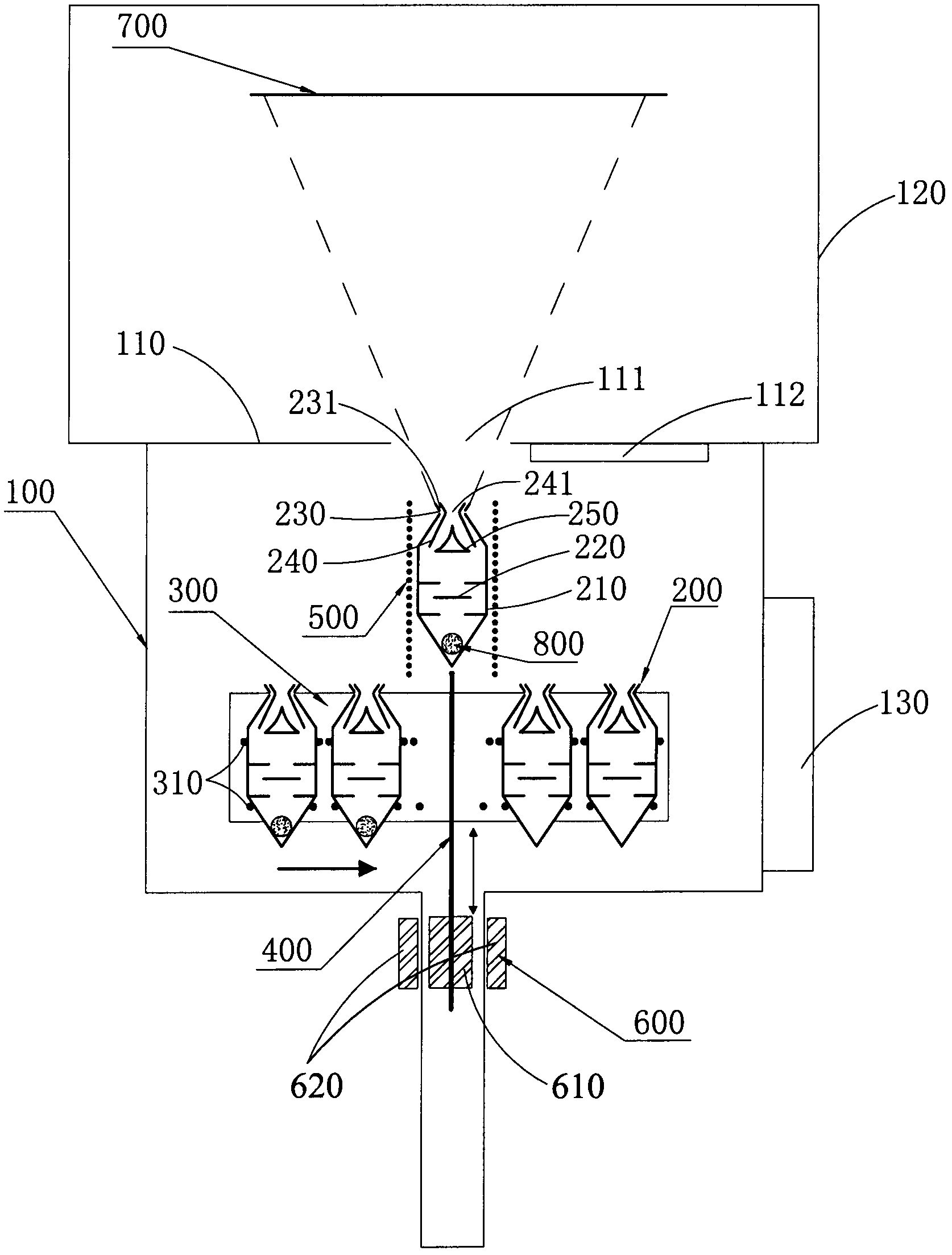
[0024] figure 1 It is a structural schematic diagram of the vacuum evaporation system in one embodiment. The vacuum evaporation system includes a vacuum chamber 100 , an evaporation source 200 , a moving frame 300 , a bracket 400 , an electromagnetic induction coil 500 and a bracket pushing device 600 . The evaporation source 200 , the moving frame 300 , the bracket 400 and the electromagnetic induction coil 500 are disposed in the vacuum chamber 100 . The bracket 400 is set at the bottom of the vacuum chamber 100 , the substrate 700 is set at the top of the vacuum chamber 100 , and the electromagnetic induction coil 500 is set above the bracket 400 and opposite to the bracket 400 . There are multiple evaporation sources 200 arranged on the mobile support 300 . The moving bracket 300 is arranged between the bracket 400 and th...


PUM


Abstract

The invention relates to a vacuum evaporation system. The vacuum evaporation system comprises a vacuum cavity chamber, evaporation sources, an electromagnetic coil and a tray. The tray is arranged on the bottom of the vacuum cavity chamber, the electromagnetic coil is arranged above the tray and opposite to the tray, the evaporation sources are multiple, the vacuum evaporation system further comprises a movable support, the multiple evaporation sources are arranged on the movable support, the movable support conveys the evaporation sources above the tray, the tray conveys the evaporation sources inside the electromagnetic coil to carry out evaporation through electromagnetic induction heating, and enables the evaporation sources to return to original positions after the evaporation is finished, and therefore the evaporation sources are arranged at the original positions on the support. The movable support moves to put the next evaporation source above the tray to carry out the next evaporation when the movable support puts the evaporation sources to the original position. The vacuum evaporation system replaces the evaporation sources through movement of the movable support, achieves continuous production, greatly simplifies the structure of a system, lowers energy consumption, improves production efficiency and controllability in a large range, and ensures product qualities.

Description

【Technical field】 [0001] The invention relates to the field of vacuum evaporation, in particular to a vacuum evaporation system. 【Background technique】 [0002] At present, the vacuum evaporation process has been widely used in the manufacture of semiconductor components and flat panel display devices. Especially organic light-emitting diodes (OLEDs) have formed a large industry. The main process in the preparation of OLEDs is vacuum evaporation, which is to put the evaporation material in a heated crucible to turn the evaporation material into steam and then deposit it. on the substrate. [0003] In the traditional vacuum evaporation system, there is only one evaporation source for evaporation, which cannot be replaced, cannot be continuously produced, and the evaporation source needs to be heated all the time. The whole system is always in a high temperature state, which not only consumes a lot of heat energy, but also causes the temperature of the entire cavity and subst...

Claims


Application Information

Patent Timeline
Patent Type & Authority Applications(China)
IPC IPC(8): C23C14/24
Inventor 张志林张建华蒋雪茵刘立宁李俊
Owner SHANGHAI UNIV
Why Eureka
Try Eureka