A design method of two-way pressure-spin uplift piles

A design method and technology of uplift piles, applied in sheet pile walls, buildings, foundation structure engineering, etc., can solve the problems of high equipment capacity requirements for static pressure piles, time-consuming and equipment-consuming bored piles, and other pile pullout performance Unsatisfactory problems, to achieve the effect of improving the bearing function, simplifying the construction method, and eliminating the piling noise

Active Publication Date: 2016-04-13
SHANDONG UNIV OF SCI & TECH
View PDF6 Cites 0 Cited by
  • Summary
  • Abstract
  • Description
  • Claims
  • Application Information

AI Technical Summary

Problems solved by technology

Screw piles have relatively good pull-out performance, but due to structural defects in the screw, the stiffness between the wire and the rod varies greatly, which is prone to stress concentration and damage, and the pull-out performance of other piles is not ideal
Bored piles consume more man-hours and equipment, the pile driver is noisy, the loss of mechanical energy is large, and the capacity of static pile pressing equipment is relatively high.

Method used


Image

  • A design method of two-way pressure-spin uplift piles
  • A design method of two-way pressure-spin uplift piles
  • A design method of two-way pressure-spin uplift piles

Examples


Embodiment Construction

[0032] Below in conjunction with accompanying drawing, introduce the two-way static pressure rotation uplift pile of the present invention.

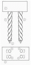
[0033] figure 1 Shown is the structural diagram of the two-way rotating pile foundation of the present invention, which is arranged symmetrically on the cap. When loading, due to the reaction force of the foundation soil, the moment generated by the pile is self-balanced under the constraints of the cap.

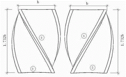
[0034] The clockwise rotating pile ② and the counterclockwise rotating pile ③ are symmetrically arranged, and their upper ends are fixedly connected with the pile cap ①. The pile point ④ is connected with the pile body ②, ③ at the lower end of the pile. ⑤ is the external curve ductile angle after the rotation of ② and ③ pile body.

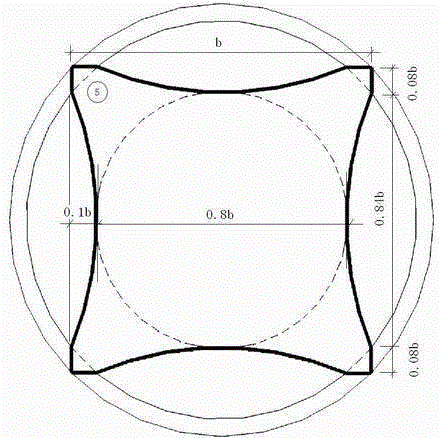
[0035] figure 2 It is the horizontal profile of the pile. According to the actual length L of the pile, the circumscribed circle is within the length of one unit, forming a space inclined surface. The a...


PUM


Abstract

A new design method for functional reinforced concrete piles-two-way pressure-rotation uplift piles, made of high-strength concrete, surrounded by four spatial rotating surfaces, and the toughness angles of the four spatial helical curves have a soil cutting angle of 60°. Under the action of pressure, it rotates and drills into the foundation soil. When rotated by 90°, the vertical distance of the same point is 1.732b. b is the side length of the square section pile. When the physical length of the pile is L, the horizontal projected end-bearing area increased by one direction is 0.333bL, and the concrete volume is reduced by 0.2848b2L. The pile foundation adopts an even number arrangement, which is divided into two types of clockwise and counterclockwise rotation. When loading, the torque formed by the reaction force of the soil can be self-balanced in the pile cap. It has advantages in improving the pull-out resistance. The inscribed circle is used as the effective design section of the reinforcement section. Due to the most effective soil cutting angle, the mechanical power consumption of the static pressure pile equipment is the lowest, and it is a prefabricated reinforced concrete functional pile suitable for factory production.

Description

technical field [0001] The invention belongs to the field of building structure foundation design, and relates to the appearance structure of a pile foundation, through which the functions of press-in, screw-in, and pull-out resistance are realized. The pile is rotated and pressed into the foundation soil by applying static pressure, which increases the contact area between the pile body and the foundation soil, has obvious comprehensive bearing capacity, saves the consumption of mechanics and avoids the noise of construction machinery. The pile is suitable for the uplift pile foundation of independent structures. Background technique [0002] The foundation under soft soil foundation conditions can use pile foundations, including prefabricated piles and cast-in-place piles. Ordinary reinforced concrete prefabricated piles are generally square, and can be designed as end-bearing piles and friction piles to bear the load on the upper part of the structure; the construction m...

Claims


Application Information

Patent Timeline
Patent Type & Authority Patents(China)
IPC IPC(8): E02D5/56E02D5/30E02D27/14
Inventor 王海超
Owner SHANDONG UNIV OF SCI & TECH
Why Eureka
Try Eureka