

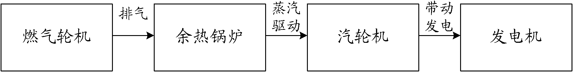
Gas-steam combined cycle power generation system
A combined cycle power generation and steam technology, which is applied in the steam generation method using heat carrier, steam engine device, combined combustion mitigation, etc.
- Summary
- Abstract
- Description
- Claims
- Application Information
AI Technical Summary
Problems solved by technology
Method used
Image

Examples
Embodiment Construction
[0028] In order to make the above objects, features and advantages of the present application more obvious and comprehensible, the present application will be further described in detail below in conjunction with the accompanying drawings and specific implementation methods.
[0029] This application redesigns the waste heat boiler system, steam turbine generator system, main transformer and other electrical systems to form a complete 60Hz combined cycle power generation system matched with SGT6-5000F gas turbine.
[0030] Since the flue gas parameters at the outlet of the SGT6-5000F gas turbine are different from those of the 50Hz gas turbines of the same scale, it is necessary to design the waste heat boiler for the new flue gas parameters.
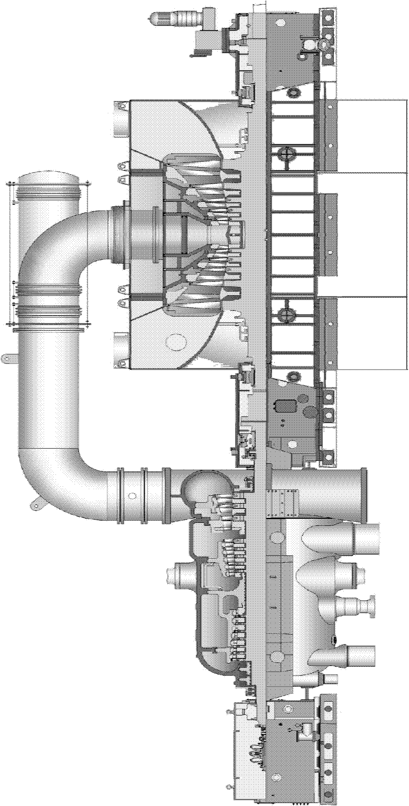
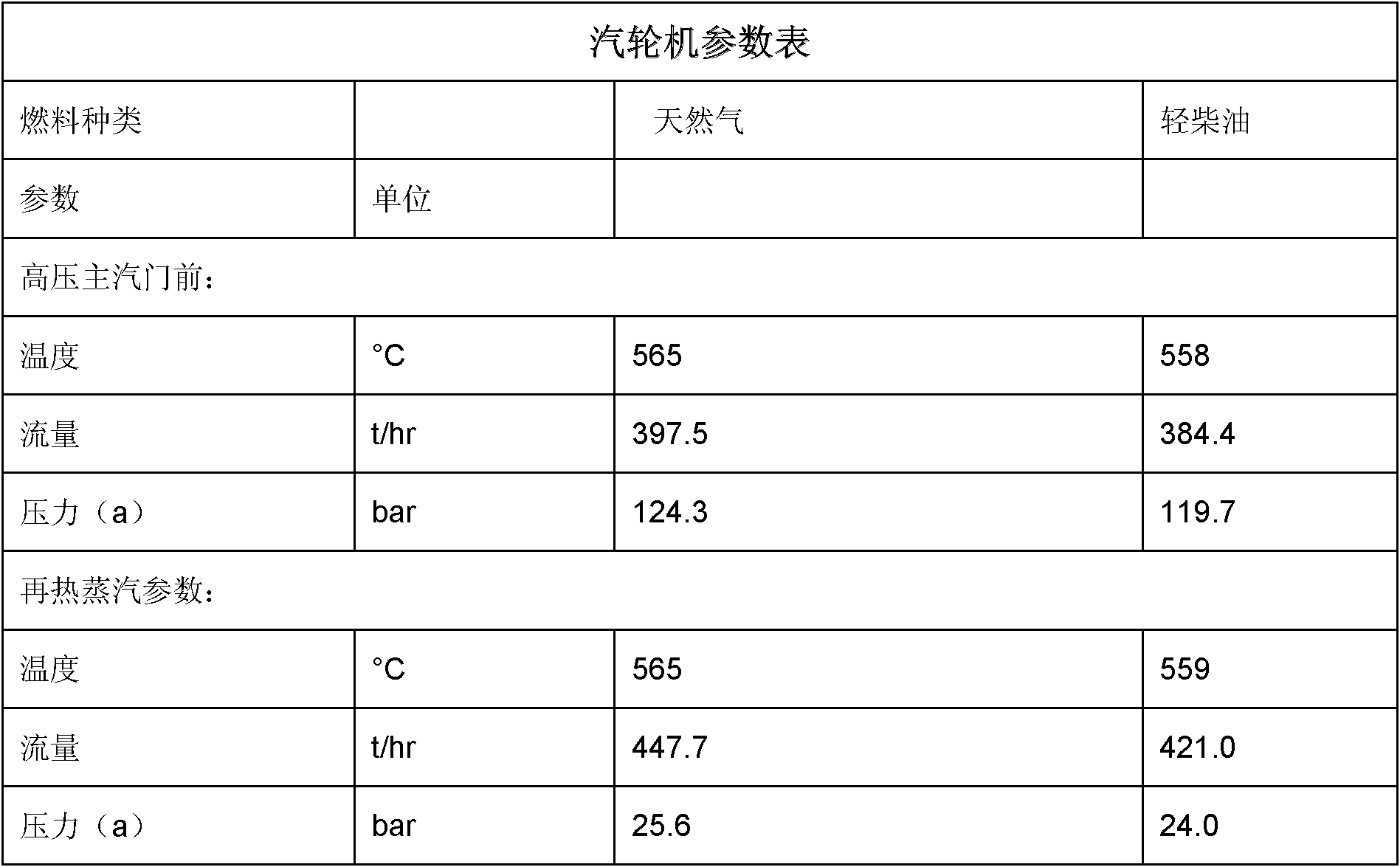
[0031] For 50Hz steam turbines and generators, they usually work at 3000rpm. Under the grid frequency of 60Hz, it is necessary to newly design the steam turbine and generator with a speed of 3600rpm, and to match the parameters of the s...
PUM
 Abstract
Description
Claims
Application Information