
High efficiency low drop-out voltage regulator

A technology of voltage regulator and low dropout voltage, which is applied in the direction of adjusting electrical variables, control/regulation systems, instruments, etc. It can solve the problems of unable to return the output voltage VOUT, increase the quiescent current of the system, and reduce the efficiency of power supply, so as to meet the requirements of The effect of current demand, improving efficiency, and avoiding low efficiency

Active Publication Date: 2014-11-05
WUXI ZGMICRO ELECTRONICS CO LTD
View PDF7 Cites 0 Cited by
  • Summary
  • Abstract
  • Description
  • Claims
  • Application Information

AI Technical Summary

Problems solved by technology

Increasing the area of ​​the power transistor MP can ensure the maximum load current when the load is working normally, but when the system is in standby or the low-dropout voltage regulator is no-load, the leakage current caused by the gate area of ​​the power transistor MP will make the output voltage VOUT Even if the error amplifier 120 is adjusted so that the gate voltage of the power transistor MP is close to the power supply voltage VBAT, the output voltage VOUT cannot return to the set voltage range, so the entire feedback loop will be in an open state
The traditional solution is to reduce the value of the voltage-dividing resistor in the voltage-dividing circuit to ensure that the leakage current of the power tube MP can be absorbed by the voltage-dividing resistor when the load current is no-load, but this also increases the system's quiescent current, reducing the efficiency of the power

Method used


Image

  • High efficiency low drop-out voltage regulator
  • High efficiency low drop-out voltage regulator

Examples


Embodiment Construction

[0019] In order to make the above objects, features and advantages of the present invention more comprehensible, the present invention will be further described in detail below in conjunction with the accompanying drawings and specific embodiments.

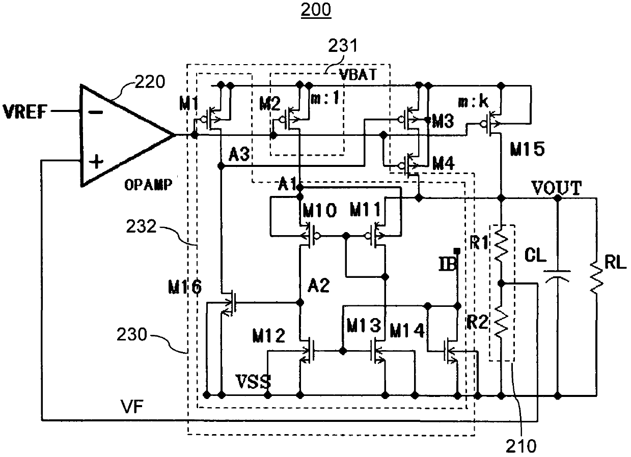
[0020] figure 2 It is a circuit diagram of the high-efficiency low-dropout voltage regulator 200 in an embodiment of the present invention. Such as figure 2 As shown, the low dropout voltage regulator 200 includes a power transistor M15 (also referred to as a preferred power transistor), a voltage divider circuit 210, an error amplifier circuit 220, and is connected in series between the output terminal VOUT of the power transistor M15 and the ground VSS capacitor CL and load resistor RL.

[0021] The source of the power transistor M15 is connected to the power supply VBAT, the gate is connected to the output terminal of the error amplifier circuit 220, and its drain is connected to the output terminal VOUT of the power transi...


PUM


Abstract

The invention provides a high efficiency low drop-out voltage regulator which comprises a preferred power tube, a bleeder circuit and an error amplifying circuit. The bleeder circuit samples output voltage of the output end of the preferred power tube to obtain feedback voltage. An error amplifier controls a grid electrode of the preferred power tube according to the feedback voltage and reference voltage. The low drop-out voltage regulator further comprises a control circuit and a backup power tube. The control circuit enables the backup power tube to provide load with current when current on the preferred power tube is larger than a set current threshold value. Otherwise the control circuit cannot enable the backup power tube to provide the load with the current. Current requirements under different load current conditions are met according to effective areas and effective width of the power tubes, wherein the effective areas and the effective width of the power tubes are changed by the load, using efficiency is improved, and the problem that efficiency is too low caused by larger leakage current of the power tubes is avoided.

Description

【Technical field】 [0001] The invention relates to the field of power management, in particular to a low dropout voltage regulator. 【Background technique】 [0002] SOC (system on chip) is the main direction of digital chip development at present. In more and more digital systems, power management chips (such as low dropout voltage regulators) and digital logic are integrated into a single chip, forming a comparative Complete system-on-chip. [0003] figure 1 A schematic circuit diagram of a conventional low dropout voltage regulator 100 is shown. The low dropout voltage regulator 100 includes a reference voltage circuit 110, an error amplifier 120, a power transistor MP, a voltage divider circuit 130, a load resistor RL and a capacitor CL. The reference voltage circuit 110 generates a reference voltage VREF that does not change with temperature, process and power supply voltage. The voltage divider circuit 130 includes a divider resistor R1 and a divider resistor R2 connec...

Claims


Application Information

Patent Timeline
Patent Type & Authority Patents(China)
IPC IPC(8): G05F1/56
Inventor 桂文明
Owner WUXI ZGMICRO ELECTRONICS CO LTD
Learn More