A catalytic layer structure that effectively reduces the pt load of fuel cells
A fuel cell and catalytic layer technology, applied in battery electrodes, structural parts, circuits, etc., can solve the problems of short development time and lack of large-scale use, and achieve the effects of improving reaction efficiency, material transfer, and catalyst utilization
- Summary
- Abstract
- Description
- Claims
- Application Information
AI Technical Summary
Problems solved by technology
Method used
Image
Examples
Embodiment 1
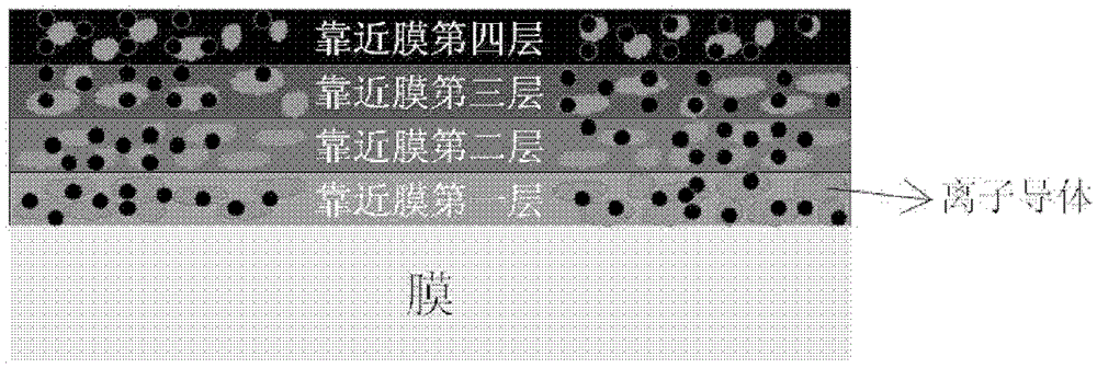
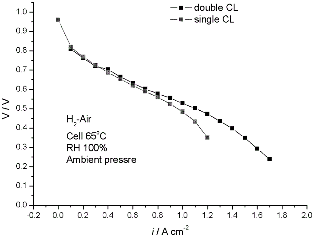
[0028] Prepare a catalytic layer structure consisting of two catalytic layers inside and outside, so that the Pt loads of the two catalytic layers are the same. The specific preparation method: first spray the first catalytic layer on the commercial Nafion membrane, and the spraying temperature is 60° , which is composed of 70wt% Pt / C catalyst and Naifon with an ion exchange equivalent of 900, and the Pt loading is 0.1mgcm -2 , the mass concentration of Nafion in the catalytic layer is 25wt.%; then the second layer of catalytic layer is sprayed, and the spraying temperature is 80°, which is composed of 40wt% Pt / C and Naifon with an ion exchange equivalent of 1100. Amount 0.1mgcm -2 , the mass concentration of Naifon in the catalytic layer is 15wt.%. figure 2 For the battery evaluation result of the prepared electrode of example 1 (operating condition during evaluation is H 2 / Air humidification temperature 65°, battery temperature 65°, H 2 The / Air stoichiometric ratio is ...
Embodiment 2
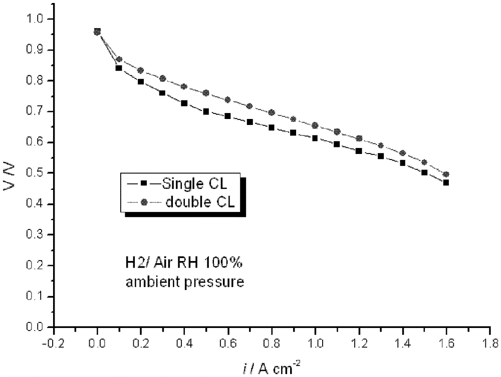
[0030] Prepare a catalytic layer structure composed of two catalytic layers inside and outside, so that the thickness of the two catalytic layers inside and outside is the same. The specific preparation method: first spray the first catalytic layer on the self-made reinforced composite membrane, and the spraying temperature is 50°. 70wt.% Pt / C catalyst and Naifon with an ion exchange equivalent of 950, Pt loading 0.28mgcm -2 , the mass concentration of Nafion in the catalytic layer is 18wt.%; then the second layer of catalytic layer is sprayed, and the spraying temperature is 70°, which is composed of 40wt% Pt / C and Naifon with an ion exchange equivalent of 1200. Amount 0.08mgcm -2 , the mass concentration of Naifon in the catalytic layer is 12wt.%. image 3 For the battery evaluation result of the prepared electrode of Example 2, the double-layer catalytic layer electrode is compared with the single-layer catalytic layer electrode in the figure (the operating condition durin...
Embodiment 3
[0032] Prepare a catalytic layer structure consisting of three catalytic layers. The specific preparation method: first, spray the first catalytic layer on the self-made reinforced composite membrane, the spraying temperature is 55°, and it is composed of 75wt.% Pt / C catalyst and ion exchange equivalent Composed of 950, Pt loading 0.12mgcm -2 , the mass concentration of Nafion in the catalytic layer is 20wt.%; then spray the second layer of catalytic layer, the spraying temperature is 65 °, which is composed of 55wt.% Pt / C and Naifon with an ion exchange equivalent of 1050, Pt Load 0.06mgcm -2 , the mass concentration of Naifon in the catalytic layer is 15wt.%; then spray the third layer of catalytic layer, the spraying temperature is 75 °, which is composed of 35wt.% Pt / C and Naifon with an ion exchange equivalent of 1150, Pt Load 0.02mgcm -2 , the mass concentration of Naifon in the catalytic layer is 11wt.%.
PUM
| Property | Measurement | Unit |
|---|---|---|
| specific surface area | aaaaa | aaaaa |
Abstract
Description
Claims
Application Information
 - R&D
- Intellectual Property
- Life Sciences
- Materials
- Tech Scout
- Unparalleled Data Quality
- Higher Quality Content
- 60% Fewer Hallucinations
Browse by: Latest US Patents, China's latest patents, Technical Efficacy Thesaurus, Application Domain, Technology Topic, Popular Technical Reports.
© 2025 PatSnap. All rights reserved.Legal|Privacy policy|Modern Slavery Act Transparency Statement|Sitemap|About US| Contact US: help@patsnap.com


