
Remote turn-off control signal receiving circuit

A technology of shutdown control and signal reception, applied in electrical components, output power conversion devices, etc., can solve problems such as power failure, achieve the effects of improving reliability, suppressing transient pulses, and solving long-term power failures

Active Publication Date: 2013-06-19
MORNSUN GUANGZHOU SCI & TECH
View PDF6 Cites 11 Cited by
  • Summary
  • Abstract
  • Description
  • Claims
  • Application Information

AI Technical Summary

Problems solved by technology

[0008] The purpose of the present invention is to provide a remote shutdown control signal receiving circuit, which can suppress transient pulses, avoid device damage, and improve product reliability; solve the problem of long-term power failure of the output voltage of the PWM switching power supply

Method used


Image

  • Remote turn-off control signal receiving circuit
  • Remote turn-off control signal receiving circuit
  • Remote turn-off control signal receiving circuit

Examples


Embodiment Construction

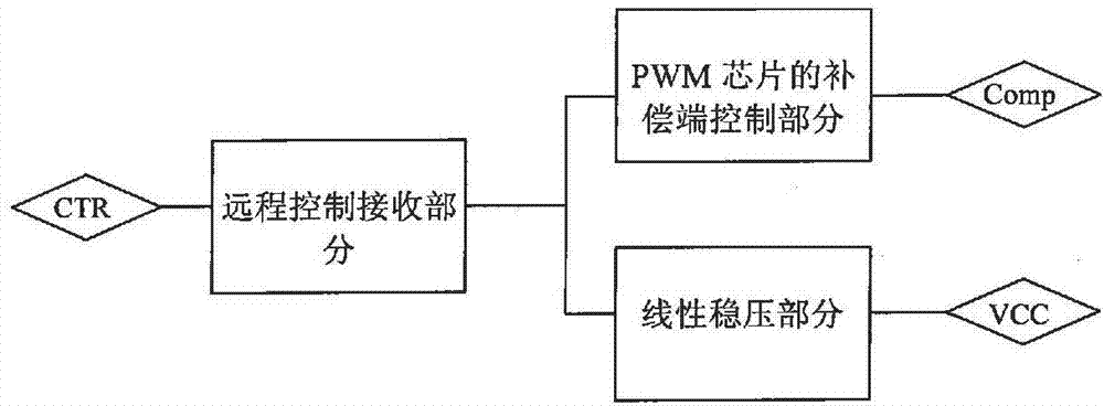
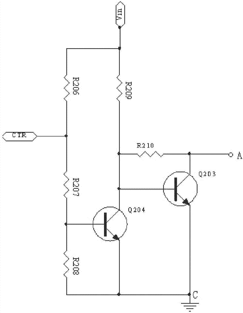
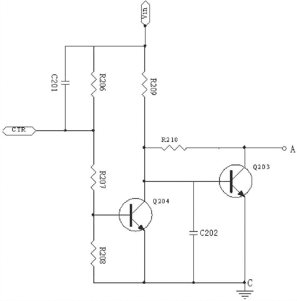
[0022] image 3 The first embodiment of the present invention is shown, including: resistors R206, R207, R208, R209, R210, transistors Q203, Q204, and capacitors C201, C202. Circuit; resistors R207, R208 and transistor Q204 form a clamping circuit. One end of the resistor R206 is connected to the input voltage, the other end of the resistor R206 is connected in series with resistors R207 and R208 to ground, the remote control terminal CTR is connected between the resistors R207 and R206; one end of the resistor R209 is connected to the input voltage vin, and the other end of the resistor R209 is connected to the collector of the triode Q204 and the base of the triode Q203, and the emitters of the two triodes Q203 and Q204 are connected to the common ground; the base of the triode Q204 is connected to the connection point of the resistors R207 and R208; the resistor R210 is connected between the base and the collector of the triode Q203; the resistor The series connection poin...


PUM


Abstract

The invention discloses a remote turn-off control signal receiving circuit. The remote turn-off control signal receiving circuit comprises a remote control end, a voltage input end, a turn-off signal input end, an audion used for outputting the turn-off signals, a biasing circuit and a clamping circuit, a first capacitor which is used for discharging transient pulse energy, and a second capacitor which is used for absorbing the transient pulse energy. The first capacitor is connected between the remote control end and the voltage input end. The second capacitor is connected between a base electrode of the audion and the ground. The value of the second capacitor is set according to remote control (RC) time constant of a biasing resistor and the second capacitor. When the transient pulse occurs, through charging of the second capacitor, time that voltage of the two ends of the second capacitor reaches the break-over voltage of the audion is greater than the duration time of the transient pulse. The value of the first capacitor needs to be set according to the size of transient pulse energy. The remote turn-off control signal receiving circuit can restrain the transient pulse, prevent damage of devices, improve reliability of products, and can solve the problem of long time power down of pulse-width modulation (PWM) switch power supply output voltage.

Description

technical field [0001] The invention relates to a signal receiving circuit, in particular to a remote shutdown control signal receiving circuit with the function of suppressing transient pulses used in a remote shutdown control circuit of a PWM switching power supply. Background technique [0002] Modern electronic power supplies have higher and higher requirements for EMC, especially for transient pulses with the characteristics of short time, high energy and randomness, such as transient pulses such as surges and static electricity. When these transient pulses are applied to the power port or control port of the PWM switching power supply with remote shutdown control function, the remote shutdown control circuit is easily disturbed by the transient pulses, causing the PWM chip to malfunction, resulting in abnormal operation of the power supply , such as system power-off, reset, etc., these abnormalities may cause adverse effects on other related industries such as communic...

Claims


Application Information

Patent Timeline
Patent Type & Authority Applications(China)
IPC IPC(8): H02M1/36H02M1/32
Inventor 廖荣军马海军
Owner MORNSUN GUANGZHOU SCI & TECH
Learn More