
An automatic carpet cutting device and method using real-time machine vision technology

An automatic cutting device, real-time vision technology, applied in the directions of transportation and packaging, sending objects, thin material processing, etc., can solve the problems of low co-seat efficiency, inability to guarantee cutting accuracy, large carpet edge error, etc., to achieve high cutting accuracy, Save photo time, low cost effect

Active Publication Date: 2015-09-30
苏州巨佳电子科技有限公司
View PDF8 Cites 0 Cited by
  • Summary
  • Abstract
  • Description
  • Claims
  • Application Information

AI Technical Summary

Problems solved by technology

[0006] Although the above two patents can realize the non-manual cutting of PVC carpet, they do not solve the problem of how to identify the edge of the carpet accurately and in real time, that is, to identify the edge of the carpet when feeding, and determine the movement route of the cutter. Therefore, in the cutting process, the cutting error of the edge of the carpet is prone to be too large, and the cutting accuracy cannot be guaranteed, and the sitting efficiency is also very low.

Method used


Image

  • An automatic carpet cutting device and method using real-time machine vision technology
  • An automatic carpet cutting device and method using real-time machine vision technology
  • An automatic carpet cutting device and method using real-time machine vision technology

Examples


Embodiment 1

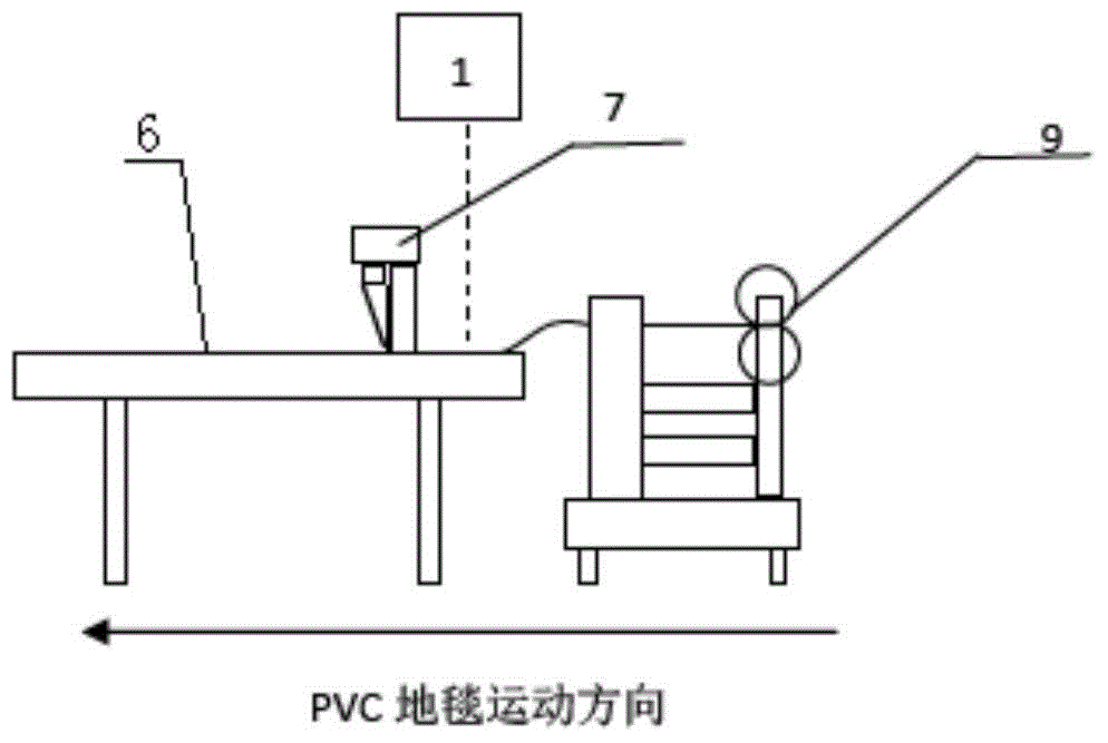
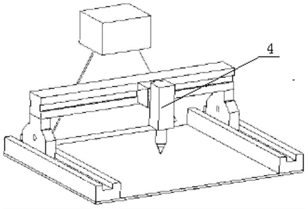
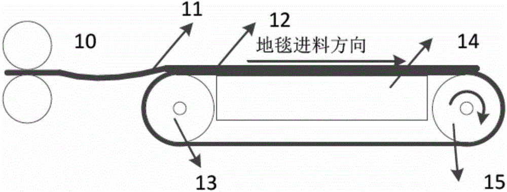
[0048] figure 1 , Picture 10 In this embodiment, it includes a cutting platform 6 which is matched with the discharge port of the pressure roller feeder 9 which includes a motor, a driving wheel and a driven wheel. There is a certain gap between the driving wheel and the driven wheel. During the heat-melting process of PVC carpet production, the PVC base material continuously moves out of the heat-melting mechanism with a fixed width. At this time, the cut carpet body, which can be rectangular sheets of various sizes, has been placed on the PVC substrate to form the PVC carpet 11. When feeding, the PVC carpet 11 is put into the gap, and the driving wheel presses the driven wheel and rotates to drive the PVC carpet 11 forward, so that the PVC carpet 11 moves to the cutting platform 6. When the PVC carpet 11 covers the cutting area of ​​the cutting platform 6, the driving wheel stops rotating.

[0049] A line scan camera 1 is provided above the feed inlet where the cutting platf...

Embodiment 2

[0068] Such as Picture 11 , Figure 11a As shown, in this embodiment, if the width of the cutting platform 6 is too large to cover the entire width direction with one line scan camera 1, multiple line scan cameras 1 can be used to coordinate work, and each line scan camera 1 Covering a part of the width direction of the cutting platform 6, the images of multiple line scan cameras 1 can cover the entire width direction when combined.

[0069] In this embodiment, two line scan cameras 1 are used, and each line scan camera 1 processes a part of the width direction of the cutting platform 6 to take pictures. The field of view of the two line scan cameras 1 may overlap partially.


PUM


Abstract

The invention relates to a carpet automatic cutting device and a carpet automatic cutting method using real-time machine vision technology. The machine vision technology, and modern motor and control technology are adopted, and therefore in the process of carpet production, manual demands are reduced and labor intensity of workers is lowered. The carpet automatic cutting device comprises a cutting platform. The cutting platform is connected with a carpet feeding device, at least one imaging device for obtaining polyvinyl chloride (PVC) carpet images which enter a cutting region in real time is arranged above the connecting position between the cutting platform and the carpet feeding device, the imaging device enables the obtained images to be sent to a processor module, the processor module identifies edges of a carpet body in the images and then determines a cutting boundary, and a motion control module is used for controlling a cutting system installed on the cutting platform, and according to the determined cutting boundary, completing cutting of a PVC carpet.

Description

Technical field [0001] The invention relates to a PVC carpet cutting device, in particular to a carpet automatic cutting device and method using real-time machine vision technology. Background technique [0002] Carpet is a very commonly used item, which has been widely used in many places such as homes, service places, factories, offices and so on. Among them, PVC carpet is the most widely used carpet. The so-called PVC carpet is to paste the carpet body on the PVC substrate sheet by hot melt. The advantages of this kind of PVC carpet are stable structure and convenient use. [0003] Traditional PVC carpet production and processing methods are divided into three steps. The first step is to cut the carpet body into a preset size; the second step is to put the carpet body on a large piece of hot-melt PVC substrate sheet; the third step, according to the size of the carpet body, the large piece of PVC carpet PVC carpet cut into small pieces. Currently the third step is done manua...

Claims


Application Information

Patent Timeline
Patent Type & Authority Patents(China)
IPC IPC(8): B65H35/06B65H43/00
Inventor 刘勇刘吉宾陈贵森
Owner 苏州巨佳电子科技有限公司
Learn More