
Device for conducting electroplating process and electroplate liquid development experiment in high-pressure environment

An electroplating process and high-voltage environment technology, applied in the electrolysis process, electrolysis components, cells, etc., can solve the problems such as the normal pressure Hall cell test device cannot meet the high-voltage reaction conditions, the insulating material is not capable of high-voltage conditions, and the electrode is easy to expand and deteriorate. , to achieve the effect of convenient application, less liquid consumption and simple equipment structure

Inactive Publication Date: 2013-06-26
江苏净视源能源环保研究院有限公司
View PDF10 Cites 22 Cited by
  • Summary
  • Abstract
  • Description
  • Claims
  • Application Information

AI Technical Summary

Problems solved by technology

[0004] In order to solve the problems of the prior art, the purpose of the present invention is to overcome the deficiencies of the prior art, to provide a device for electroplating process and electroplating solution development test in a high-pressure environment, and to solve the problem that the normal-pressure Hall cell test device cannot meet the requirements of high-pressure reaction. Condition defects, and overcome the insulation materials such as plexiglass or hard polyvinyl chloride commonly used in the atmospheric pressure Hall cell test device are not suitable for high pressure conditions, especially supercritical or subcritical CO 2 The problem of easy expansion and deterioration and electrode sealing and insulation can easily obtain the electroplating effect of the plating solution in a wide range of current density in a short time. 2 Assist in electroplating process research, electroplating solution formulation development and electroplating process control in the presence of

Method used


Image

  • Device for conducting electroplating process and electroplate liquid development experiment in high-pressure environment
  • Device for conducting electroplating process and electroplate liquid development experiment in high-pressure environment
  • Device for conducting electroplating process and electroplate liquid development experiment in high-pressure environment

Examples


Embodiment 1

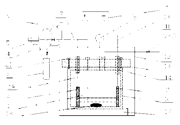
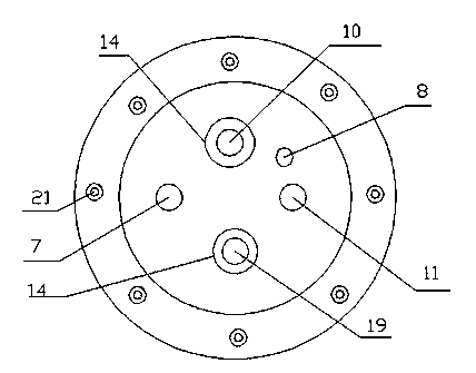
[0022] see figure 1 with figure 2 , in this embodiment, a kind of device that carries out electroplating process and electroplating solution development test under high pressure environment, comprises ladder-shaped reactor 1, anode 2, negative electrode 15 and external power supply 9, holds electroplating solution in trapezoidal reactor 1, An anode 2 and a cathode 15 are respectively placed on the non-parallel opposite sides of the trapezoidal reactor 1 to form a two-electrode system. The anode 2 is connected to the positive end of the external power supply 9 through the anode electrode wire 19, and the cathode 15 is connected to the external power supply 9 through the cathode electrode wire 10. The negative terminal of the high-voltage electrochemical reactor, CO 2 The conveying system, pressure control system, temperature control system and stirring system, the trapezoidal reactor 1 is set inside the high-pressure electrochemical reaction kettle, and the external power sup...

Embodiment 2

[0029] This embodiment is basically the same as Embodiment 1, especially in that:

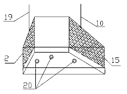
[0030] In this example, see image 3 , by using polytetrafluoroethylene fixing bolts 20, the trapezoidal reactor 1 is fixedly connected and installed with the high-pressure electrochemical reactor. The fixing bolts are made of polytetrafluoroethylene, which solves the problem that insulating materials such as plexiglass or hard polyvinyl chloride commonly used in the atmospheric pressure Hall cell test device are not suitable for high pressure conditions, especially in supercritical or subcritical CO 2 It is easy to expand and deteriorate and the electrode insulation and sealing problems in the middle, it is convenient to obtain the electroplating effect of the plating solution in a wide range of current density in a high-voltage environment in a short time, and it is suitable for high-voltage CO 2 The development of electroplating process, the formulation of electroplating solution and the de...

Embodiment 3

[0032] This embodiment is basically the same as the previous embodiment, and the special features are:

[0033] In this embodiment, at least one layer of polytetrafluoroethylene insulating layer is wrapped around the wire section of the wire section where the anode electrode wire 19 and the cathode electrode wire 10 enter the high-voltage electrochemical reactor, which can adapt to the supercritical CO 2 or subcritical CO 2 Conduct Hall cell tests in homogeneous and multiphase systems composed of conductive solutions, and use polytetrafluoroethylene insulating coatings to achieve the purpose of insulating electrode wires.


PUM


Abstract

The invention discloses a device for conducting electroplating process and electroplate liquid development experiment in a high-pressure environment. The device comprises a trapezoid reactor, an anode, a cathode, an external power supply, a high-pressure electrochemical reaction kettle, a CO2 conveying system, a pressure control system, a temperature control system and a stirring system, as well as an insulating sealing structure which is applicable to connection of electrodes with reaction containers under high-pressure condition. By utilizing the device, the defect that a normal-pressure Hull cell experiment device cannot meet the high-pressure reaction condition is solved, the problems that insulating materials such as organic glass or rigid polyvinyl chloride and the like generally used by the normal-pressure Hull cell experiment device cannot meet the high-pressure condition, particularly, the materials are easy to swell and degrade and the electrodes are sealed in an insulating manner in supercritical or subcritical CO2, are overcome, an electroplating effect that liquid is plated within a wider current density range can be conveniently achieved in short time, and help is provided for electroplating process research, electroplating liquid formula development and electroplating process control on the presence of high-pressure CO2.

Description

technical field [0001] The invention relates to a high-voltage electrochemical experimental reaction equipment, especially an instrument and equipment for electroplating research and electroplating process control, using supercritical CO 2 or subcritical CO 2 Conduct Hall cell tests in homogeneous and multi-phase systems composed of conductive solutions, and apply to electroplating process and electroplating solution development tests in high-voltage environments. Background technique [0002] The electroplating process is a surface treatment technology that uses electrochemical principles to deposit metal or alloy coatings on the substrate. It is one of the most important methods for the preparation of metal film materials and has been widely used in various industries of the national economy. At present, the rapid development of modern industry and technology has put forward higher requirements for the environmental protection of the electroplating process and the functio...

Claims


Application Information

Patent Timeline
Patent Type & Authority Applications(China)
IPC IPC(8): C25D17/00C25D21/12C25D21/10C25D21/00
Inventor 鄢浩
Owner 江苏净视源能源环保研究院有限公司
Learn More