Cold-region used multi-connected heat pump system and control method thereof

A heat pump system and technology in cold regions, applied in the multi-connected heat pump system and its control field using the technology of supplementing air to increase enthalpy, it can solve the problems of large flow pressure loss, large subcooling degree, etc.

Active Publication Date: 2013-06-26
QINGDAO HISENSE HITACHI AIR CONDITIONING SYST
View PDF5 Cites 25 Cited by
  • Summary
  • Abstract
  • Description
  • Claims
  • Application Information

AI Technical Summary

Problems solved by technology

But for the existing multi-connected heat pump system, since one outdoor unit in the multi-connected heat pump system needs to be connected to multiple indoor units through long piping, and the high-pressure liquid refrigerant flows in the long piping, the pres

Method used


Image

  • Cold-region used multi-connected heat pump system and control method thereof
  • Cold-region used multi-connected heat pump system and control method thereof
  • Cold-region used multi-connected heat pump system and control method thereof

Examples


Embodiment 1

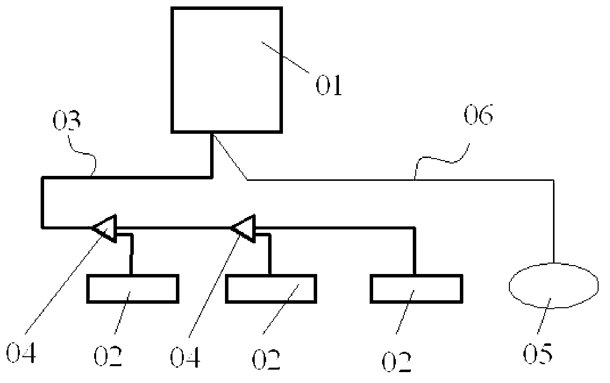
[0070] figure 2 A simplified structure diagram of the multi-connected heat pump system in the present invention is shown. Such as figure 2 As shown, it includes one or more outdoor units 01, one or more indoor units 02, refrigerant pipeline 03, branch pipe 04, control unit 05 and communication line 06. A plurality of outdoor units 01 form an outdoor unit, and the control unit 05 controls the outdoor unit through a communication line 06 . The outdoor unit 01 is connected to the indoor unit 02 through a refrigerant pipeline 03 and a branch pipe 04 .

[0071] In this embodiment, the multi-connected heat pump system includes one outdoor unit 01 and two indoor units 02 . Certainly, the numbers of outdoor units 01 and indoor units 02 of the multi-connected heat pump system in this embodiment are only exemplary, and the specific numbers of outdoor units 01 and indoor units 02 are determined according to the actual needs of users.

[0072] The working principle of the present in...

Embodiment 2

[0133] The structure of the multi-connected heat pump system in Embodiment 2 is similar to that of the multi-connected heat pump system in Embodiment 1. The difference is that in the outdoor unit, the first refrigerant branch circuit and the second refrigerant branch circuit share a heat exchanger, that is, the fourth heat exchanger 7.

[0134] For the convenience of description, the specific structure of one outdoor unit and one indoor unit is still used to illustrate the working principle of the multi-connected heat pump system in this embodiment.

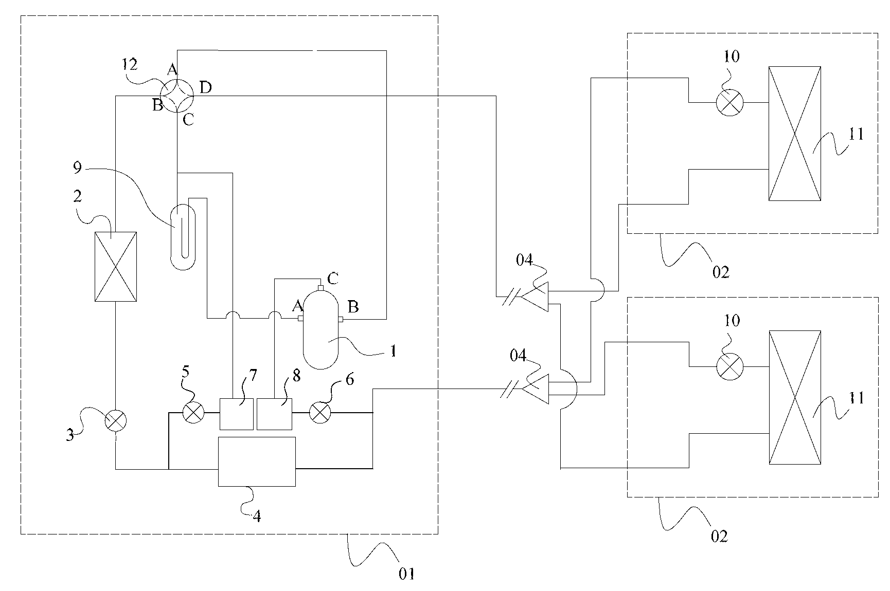
[0135] Figure 7 A schematic structural diagram of the multi-connected heat pump system in Embodiment 2 is shown. Such as Figure 7 As shown, the outdoor unit of the multi-connected heat pump system is equipped with a compressor 1, a first heat exchanger 2, a first electronic expansion valve 3, a third heat exchanger 4, a second electronic expansion valve 5, and a third electronic expansion valve 6. The fourth heat exchanger 7...

Embodiment 3

[0147] The multi-connected heat pump system in Embodiment 3 is similar in structure to the multi-connected heat pump system in Embodiment 2, the difference is that the heat exchanger in the main refrigerant circuit is shared with the first refrigerant branch circuit and the second refrigerant branch circuit The heat exchanger is integrated as a sixth heat exchanger 32 . The third heat exchanger 4 in the main refrigerant circuit and the fourth heat exchanger 7 shared by the first refrigerant branch circuit and the second refrigerant branch circuit are two parts of the sixth heat exchanger 32 . Figure 8 A schematic structural diagram of the multi-connected heat pump system in Embodiment 3 is shown. Such as Figure 8 As shown, the main refrigerant circuit runs through one heat exchange channel in the sixth heat exchanger 32 , and the first refrigerant branch circuit and the second refrigerant branch circuit run through another heat exchange channel in the sixth heat exchanger 3...


PUM


Abstract

The invention discloses a cold-region used multi-connected heat pump system and a control method of the multi-connected heat pump system. The multi-connected heat pump system comprises a first refrigerant branch and a second refrigerant branch. The first refrigerant branch is connected between a first heat exchanger and a compressor of a main refrigerant loop in a crossed mode. A control unit controls the main refrigerant loop and when the main refrigerant loop is in refrigeration working condition, and the first refrigerant branch splits refrigerant flowing out the first heat exchanger; split refrigerant exchanges heat with the refrigerant flowed into a second heat exchanger after the split refrigerant is throttled and depressurized in the first refrigerant branch, the temperature of the refrigerant flowed into a second heat exchanger is decreased, and then the split refrigerant flows back to the main refrigerant loop to enter the compressor. The second refrigerant branch is connected between the second heat exchanger and a compressor of a main refrigerant loop in a crossed mode. The second refrigerant branch splits refrigerant flowing out the second heat exchanger. Split refrigerant exchanges heat with the refrigerant flowed into the main refrigerant loop after the split refrigerant is throttled and depressurized in the second refrigerant branch, and then the split refrigerant turns into gaseous refrigerant and is injected into the compressor to decrease the temperature of refrigerant vapor in the compressor.

Description

technical field [0001] The invention relates to the technical field of multi-connected heat pumps, in particular to a multi-connected heat pump system and a control method thereof which adopt the technology of supplementing air to increase enthalpy and are used in cold regions. Background technique [0002] At present, the cold regions in northern my country mainly rely on coal or gas for heating in winter, but long-term reliance on coal and gas for heating will cause serious air pollution. As a clean and energy-saving heating method, the air source heat pump system has been widely concerned. However, if the air source heat pump system is extended to the cold northern regions without any improvement, as the ambient temperature decreases in the winter heating season, its heating coefficient will be limited by the characteristics of the vapor compression cycle and will rapidly decay. As the outside temperature drops rapidly, the heat demand rises rapidly with the drop of outs...

Claims


Application Information

Patent Timeline
IPC IPC(8): F25B30/02F25B41/04F25B41/06F25B49/02F25B41/20F25B41/34F25B41/40
CPCY02B30/70
Inventor 刘敏李亚军丛辉
Owner QINGDAO HISENSE HITACHI AIR CONDITIONING SYST
Why Eureka
Try Eureka