Heat exchanger with convertible flow path and application method thereof

A heat exchanger and process technology, which is applied to the heat exchanger shell, heat exchange equipment, evaporator/condenser, etc. Insufficient, low condensation pressure and other problems, to achieve the effect of improving reliability and safety, reducing energy consumption, and reducing evaporation temperature

Active Publication Date: 2013-06-26
NANJING JINDIAN REFRIGERANT IND
View PDF6 Cites 9 Cited by
  • Summary
  • Abstract
  • Description
  • Claims
  • Application Information

AI Technical Summary

Problems solved by technology

Most of the general central air-conditioning systems use water-cooled chillers as the main engine. The existing water-cooled chillers use constant-flow heat exchangers as evaporators and condensers. This constant-flow heat exchanger is used in variable flow systems. When As the water flow changes with the load, the water flow rate and water resistance will change, which will affect the heat transfer effect of the heat exchanger and the energy consumption of the system.
[0004] In addition, general heat exchangers cannot realize the change of heat exchange area during use. Annual refrigeration or heating process conditions, etc.) Due to the high temperature of the evaporator outlet water or the low temperature of the condenser water inlet, and the compressor often operates at

Method used


Image

  • Heat exchanger with convertible flow path and application method thereof
  • Heat exchanger with convertible flow path and application method thereof
  • Heat exchanger with convertible flow path and application method thereof

Examples


Embodiment

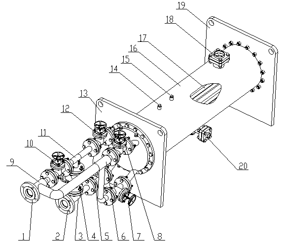
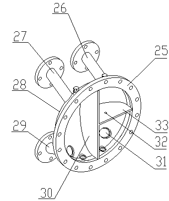
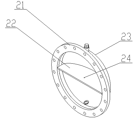
[0026] Example: A kind of heat exchanger of the present invention can convert process, as figure 1 As shown, it includes housing 16, heat exchange tube 17, front tube plate 13, rear tube plate 19, front water chamber assembly 25, rear water chamber assembly 21, water inlet 2, water outlet 1, refrigerant gas interface 18, refrigeration Liquid interface 20, safety valve seat 14, inspection valve seat 15, A valve 12, B valve 8, C valve 7, D valve 5, E valve 4, F valve 10, three-way deh3, three-way bcg6, three-way fgj9 and Tee aef11, the planes of the front tube plate 13 and the rear tube plate 19 are respectively abutted against the two ports of the housing 16, as Figure 4 , 5 As shown, the front tube sheet 13 and the rear tube sheet 19 respectively have four groups of tube holes 37: Group A, Group B, Group C and Group D, and the heat exchange tubes 17 pass through the corresponding tube holes 37 and the front tube sheet 13. It is expanded and fixed with the rear tube plate ...


PUM


Abstract

The invention discloses a heat exchanger with convertible flow path. An internal space between a front flanging end enclosure and a front tube plate is divided into two sides by a vertical separating rib from a vertical plane. One side is divided into an upper side and a lower side by a horizontal separating plate in a horizontal plane. An internal space between a rear flanging end enclosure and a rear tube plate is divided into an upper side and a lower side by a separating rib. A heat exchange tube flow path region corresponding to tube holes is a flow path A, wherein the tube holes are formed above a horizontal separating rib which is arranged at one side of the vertical separating rib. A heat exchange tube flow path region corresponding to tube holes formed below the horizontal separating rib is a flow path D. A heat exchange tube flow path region corresponding to tube holes is a flow path B, wherein the tube holes are formed in the other side of the vertical separating rib and above the separating rib. A heat exchange tube flow path region corresponding to tube holes formed below the separating rib is a flow path C. According to functions of water chamber flow path division and a conversion valve, the heat exchanger is switched between the second flow path and the fourth flow path, heat exchanging areas are further reduced by half under the working condition of the second flow path, heat exchange efficiency is obviously improved, operational energy consumption is reduced, and reliability and safety are guaranteed under the poor working condition.

Description

technical field [0001] The invention relates to a heat exchanger, in particular to a heat exchanger with a switchable process flow and a use method thereof. Background technique [0002] At present, in the cold regions of northern my country, the traditional centralized heating method is mainly coal-fired. This heating method has great problems in terms of energy saving, environmental protection and safety, especially the large amount of smoke and dust emissions caused by coal-fired. In some northern cities, severe weather phenomena such as smog and PM2.5 seriously exceed the standard frequently occur in winter. Therefore, in recent years, the country has vigorously promoted clean heating methods. Many buildings use water source heat pump units as heating hosts to replace traditional coal-fired Boilers, and mainly water-water type water source heat pump units. The cooling and heating mode conversion of the existing water-water type water source heat pump units on the market b...

Claims


Application Information

Patent Timeline
IPC IPC(8): F25B39/00F28F9/02F28F27/00
Inventor 王雪峰
Owner NANJING JINDIAN REFRIGERANT IND
Why Eureka
Try Eureka