
Gradient amplifier system and control method thereof

A gradient amplifier and amplifier technology, applied in the direction of instruments, scientific instruments, measuring magnetic variables, etc., can solve the problems of increased power loss, different switching frequencies, large thermal stress of gradient amplifiers, etc., and achieve the effect of reducing power loss and thermal stress

Active Publication Date: 2013-06-26
GENERAL ELECTRIC CO
View PDF10 Cites 26 Cited by
  • Summary
  • Abstract
  • Description
  • Claims
  • Application Information

AI Technical Summary

Problems solved by technology

However, in conventional gradient amplifier systems, each of the bridges has a different direct current (DC) link voltage and a different voltage command, which causes each bridge to apply a different switching frequency
Since each bridge operates at a different switching frequency with a different DC link voltage, there is considerable power loss in the gradient amplifier system
Also, when low voltages are desired across the gradient coils, power losses increase
In addition, the power loss is unevenly distributed across the bridges and the loading on each bridge is different, which results in a large thermal stress on the gradient amplifier

Method used


Image

  • Gradient amplifier system and control method thereof
  • Gradient amplifier system and control method thereof
  • Gradient amplifier system and control method thereof

Examples


Embodiment Construction

[0030]Specific implementations of the present invention will be described below. It should be noted that in the process of specific descriptions of these implementations, for the sake of concise description, it is impossible for this specification to describe all the features of the actual implementations in detail. It should be understood that, in the actual implementation process of any embodiment, just like in the process of any engineering project or design project, in order to achieve the developer's specific goals and to meet system-related or business-related constraints, Often a variety of specific decisions are made, and this can vary from one implementation to another. In addition, it will be appreciated that while such development efforts may be complex and lengthy, the technology disclosed in this disclosure will be Some design, manufacturing or production changes based on the content are just conventional technical means, and should not be interpreted as insuffici...


PUM


Abstract

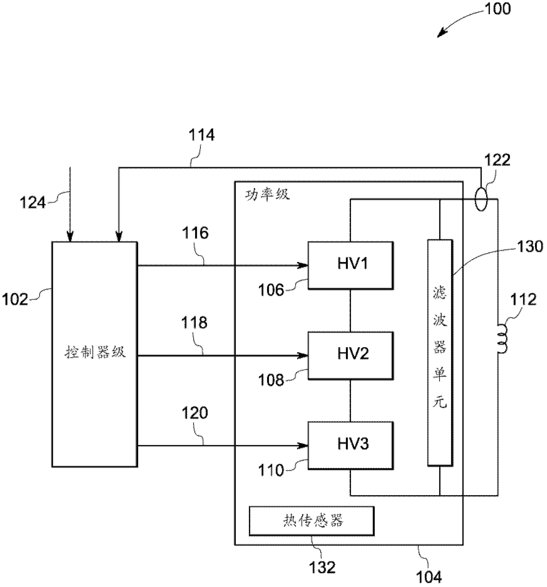
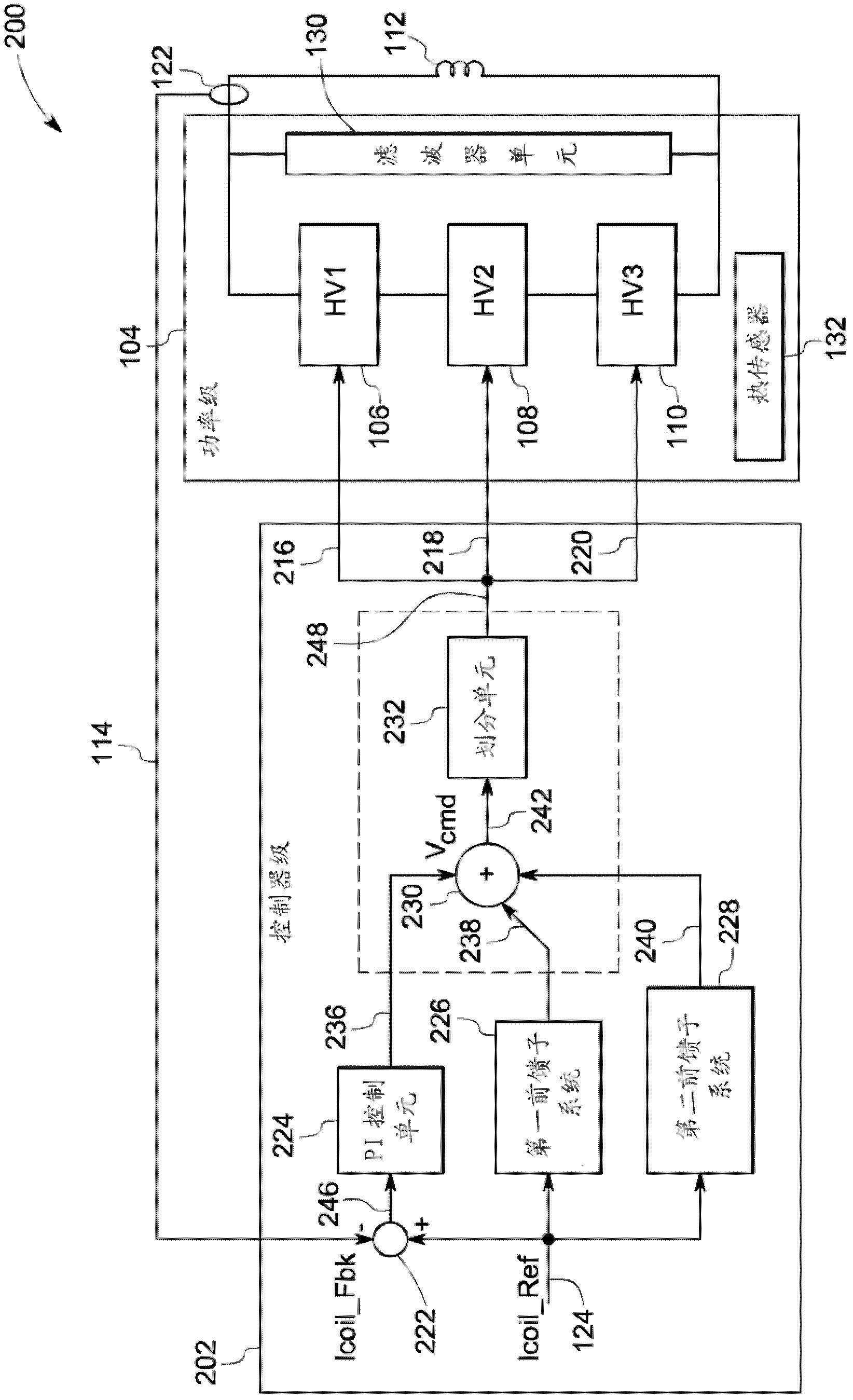
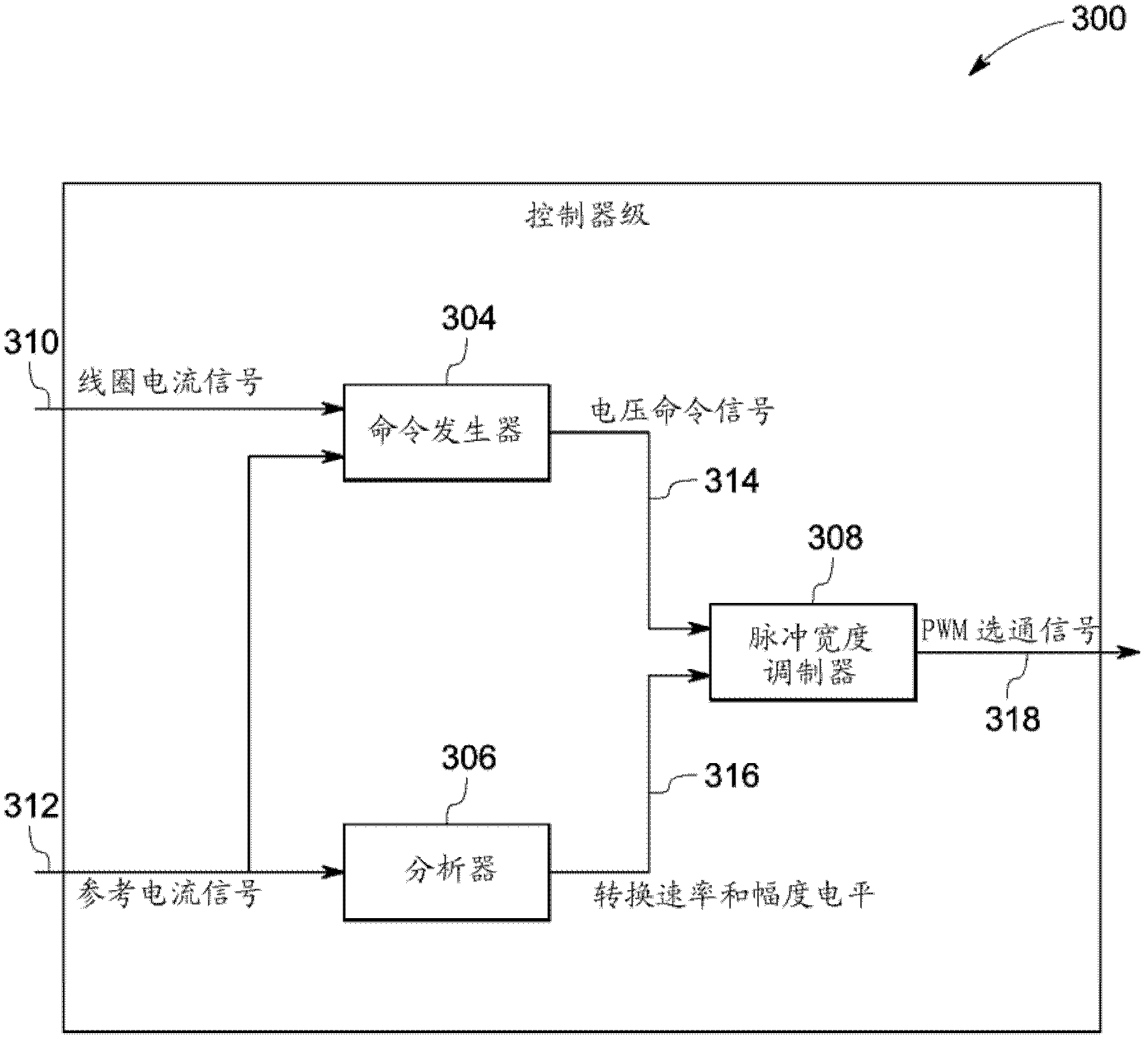
A gradient amplifier system comprises a power level, a gradient coil and a controller level, wherein the power level comprises a plurality of bridge amplifiers which are operated at first switching frequency, the gradient coil is coupled to the power level and configured to generate a magnetic field which is proportional to coil current signals supplied by the power level, and the controller level is coupled to the input end of the power level and configured to generate gating signals of the pulse width modulation on basis of the coil current signals and reference current signals. When the conversion rate which is relative to the reference current signals and occurs in at least a first time period is lower than the preset threshold rate, the gating signals of the pulse width modulation are generated at second switching frequency, and the generated gating signals of the pulse width modulation are applied to the power level to switch the operating frequency of every bridge amplifier from the first switching frequency to the second switching frequency.

Description

technical field [0001] The invention relates to a magnetic resonance imaging (MRI) system, in particular to a gradient amplifier system used in the MRI system and a control method thereof. Background technique [0002] In only a few decades, the use of Magnetic Resonance Imaging (MRI) scanners has grown enormously. MRI scans are increasingly being used to aid in the diagnosis of multiple sclerosis, brain tumors, torn ligaments, tendinitis, cancer, stroke, and more. MRI is a non-invasive medical testing technique that assists physicians in the diagnosis and treatment of various medical conditions. The enhanced contrast provided by MRI scans between the different soft tissues of the body allows doctors to better evaluate parts of the body and determine the presence of certain diseases that may not be available using methods such as x-rays, ultrasound, or computed tomography (CT) to adequately assess other single imaging methods. [0003] Typically, conventional MRI systems ...

Claims


Application Information

Patent Timeline
Patent Type & Authority Applications(China)
IPC IPC(8): G01R33/385G01R33/20
CPCG01R33/3852G01R33/3614G01R33/543
Inventor J.A.萨巴特W.M.史格芬顿迟颂赖日新施贻蒙张艳军
Owner GENERAL ELECTRIC CO
Learn More