Multifunctional electromagnetic stirrer

An electromagnetic stirrer and electromagnetic stirring technology, applied in the field of continuous casting electromagnetic stirring, can solve the problems of unfavorable power grid function and stability, failure to meet process requirements, small central magnetic field, etc., and achieve simple and ingenious connection method, simple structure and small size Effect

Active Publication Date: 2013-07-03
BAOSHAN IRON & STEEL CO LTD
View PDF8 Cites 28 Cited by
  • Summary
  • Abstract
  • Description
  • Claims
  • Application Information

AI Technical Summary

Problems solved by technology

The advantage of this electromagnetic stirring is that it only uses a set of traveling wave coil windings and a set of power supply, and the conversion of different stirring functions can be realized by changing the coil connection mode; the problem with this stirring device is that there are four independent salient pole type When the linear inductor works in a traveling wave magnetic field, the magnetic circuit closes better, but when the coil connection is changed to a rotating magnetic field, the magnetic fiel

Method used


Image

  • Multifunctional electromagnetic stirrer
  • Multifunctional electromagnetic stirrer
  • Multifunctional electromagnetic stirrer

Examples


Embodiment 1

[0026] Embodiment one structure of the present invention

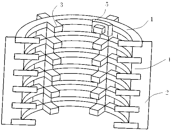
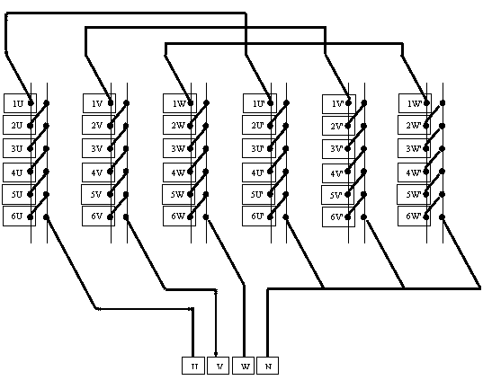
[0027] see figure 1 , is a cross-sectional schematic diagram of a multifunctional electromagnetic stirrer embodiment 1 of the present invention (the stirrer shell and other components are not shown), the multifunctional electromagnetic stirrer of the present invention includes an annular iron core 1, a rack iron core 2. Annular iron core salient pole 3, rack iron core salient pole 4 and electromagnetic coil winding 5, annular iron core 1 is horizontal, divided into six upper and lower layers at equal intervals, and the inner wall of each layer is respectively equipped with six annular iron cores. The core salient pole 3; the rack core 2 is vertically arranged, and there are six uniformly distributed on the outer circumference of the annular iron core 1, and each bar contains five equally spaced rack core salient poles 4, and the rack core 4 The salient poles of the ring iron core 1 are respectively inserted into the i...

Embodiment 2

[0033] Embodiment two structure of the present invention

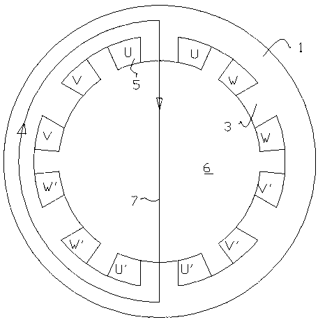
[0034] Such as Figure 8 It is a cross-sectional schematic diagram of another embodiment of the multifunctional electromagnetic stirrer of the present invention. A multifunctional electromagnetic stirrer includes six layers of horizontally arranged second annular iron cores 8, six vertically arranged second rack iron cores 9 and Thirty-six identical electromagnetic coil windings 5; each of the six second rack cores 9 has six salient poles 10, and the second annular core 8 is set on the outer circumference of the second rack core 9 , the second annular iron core 8 is divided into six layers up and down, and each layer of the second annular iron core 8 corresponds to the six salient poles 10 of the second rack iron core 9; Each salient pole 10 of the bar iron core 9 is supplied with three-phase low-frequency alternating current by a variable frequency power supply.

[0035] The difference between the structure of the s...


PUM


Abstract

The invention discloses a multifunctional electromagnetic stirrer, comprising six layers of annular cores (1) which are horizontally arranged, six rack cores (2) which are vertically arranged and thirty-six identical solenoid coil windings (5); the six layers of annular cores are mutually independent layer by layer, are aligned vertically and are separated at intervals; the inner wall of each layer of annular core is provided with six salient poles (3); the six rack cores are uniformly distributed on the outer walls of the annular cores; each rack core is provided with five salient poles (4); the salient poles of the rack cores are inserted into the intervals, which are vertically separated, of the annular poles; the salient poles of each rack core and the salient poles of the six layers of annular cores are located on the same circumference; the top surfaces of the salient poles of each rack core are inserted into the inner walls between the salient poles of the annular cores; the thirty-six solenoid coil windings are respectively sleeved on each salient pole of the annular cores; and three-phase low-frequency alternating current is supplied by a variable-frequency power source. According to the multifunctional electromagnetic stirrer, the structure is simple, the size is small, magnetic leakage is small, and the working efficiency is high.

Description

technical field [0001] The invention relates to the technical field of continuous casting electromagnetic stirring, in particular to a multifunctional electromagnetic stirrer and an electromagnetic winding connection method for round billet continuous casting. Background technique [0002] A few days ago, electromagnetic stirring has become one of the standard equipment in modern continuous casting production, which plays a vital role in smooth production and improving the quality of slab. According to the installation position of electromagnetic stirring on the continuous casting machine, there are mold electromagnetic stirring, secondary cooling electromagnetic stirring and terminal electromagnetic stirring, etc., or these different types of electromagnetic stirring can be used in combination on the casting machine at the same time. However, no matter where these electromagnetic stirrers are installed in the casting machine or how they are used in combination, the way ...

Claims


Application Information

Patent Timeline
IPC IPC(8): B22D11/115
Inventor 侯晓光刘俊江周月明王洪兵胡子国吴存有关运泽
Owner BAOSHAN IRON & STEEL CO LTD
Why Eureka
Try Eureka