
One-time dust removal system for revolving furnace

A technology of dust removal system and converter, applied in the field of steelmaking dust removal, can solve problems such as environmental pollution, reduced dust removal efficiency, high temperature dry flue gas overflow, etc., and achieve the effects of preventing environmental pollution, improving dust removal efficiency, and preventing burnout

Active Publication Date: 2013-07-03
北京明诚环保科技有限公司
View PDF5 Cites 3 Cited by
  • Summary
  • Abstract
  • Description
  • Claims
  • Application Information

AI Technical Summary

Problems solved by technology

[0006] 1. Due to the structural design of the rapid overflow cooling tower, the water in the overflow tank will overflow into the inner wall of the tower unevenly, which will cause local overheating of the inner wall of the rapid overflow cooling tower, thus endangering the strength and stability of the tower body. normal work;
[0007] 2. Due to the uneven overflow, there will be a dry-wet interface on the inner wall of the tower, and the dust will stick to the inner wall, which will affect the flow and heat exchange of dry flue gas;
[0008] 3. Since the high-temperature dry flue gas must first pass through the inner side of the connection between the vaporization cooling flue and the rapid overflow cooling tower and the water seal plate, the inner side of the joint and the water seal plate are greatly affected by the high-temperature dry flue gas. Therefore, the inner side of the connection between the vaporization cooling flue and the rapid overflow cooling tower and the water seal plate are easy to burn out, resulting in the overflow of high-temperature dry flue gas and it is difficult to fully enter the rapid overflow cooling tower, resulting in environmental pollution and a reduction in dust removal efficiency. ;
The associated problem is that the larger the stroke of the mound (and the larger the stroke of the driving device), the more difficult and insensitive the vertical movement of the mound after being covered.

Method used


Image

  • One-time dust removal system for revolving furnace
  • One-time dust removal system for revolving furnace
  • One-time dust removal system for revolving furnace

Examples


Embodiment Construction

[0073] The present invention will be described in further detail below in conjunction with the accompanying drawings and specific embodiments, but not as a limitation of the present invention.

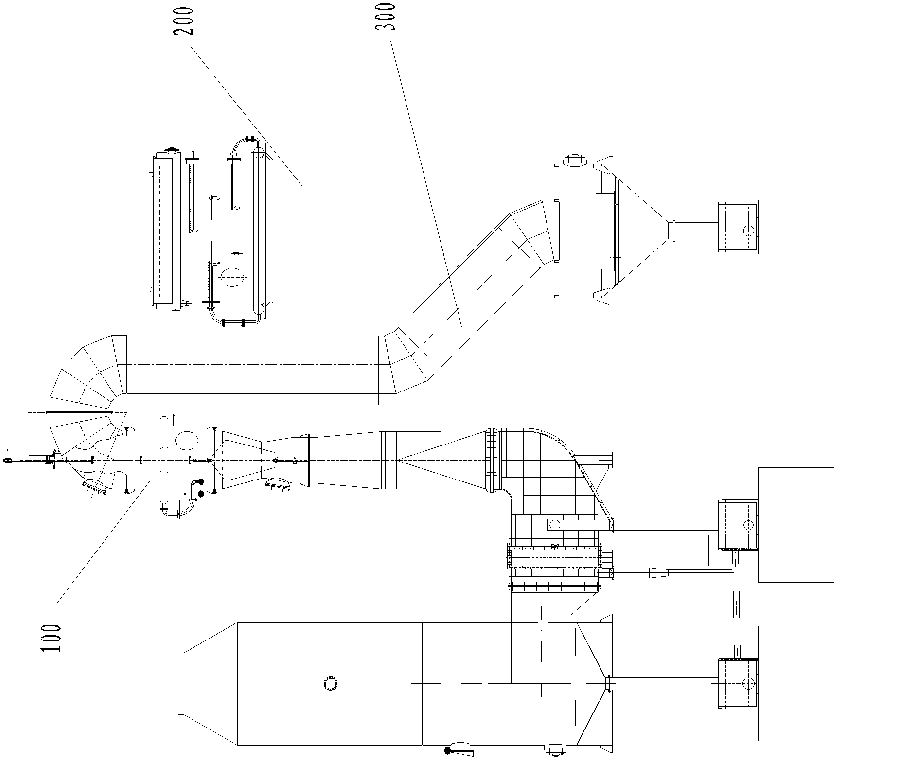
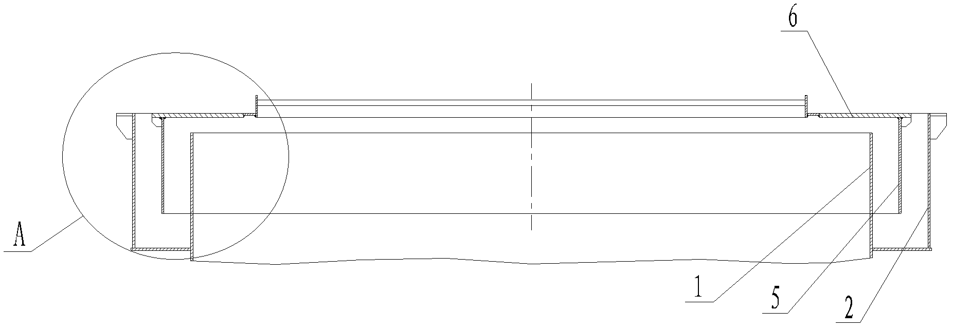
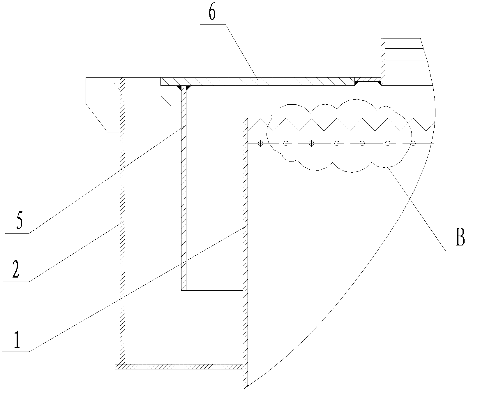
[0074] Such as figure 1 As shown, the converter primary dust removal system of the present invention includes a rapid overflow cooling tower 200 and an adjustable venturi tube 100 , and the middle and lower part of the rapid overflow cooling tower 200 is connected to the adjustable venturi tube 100 through a connecting elbow 300 . Such as figure 2 As shown, the top of the tower body 1 of the rapid overflow cooling tower 200 is provided with an overflow water tank 2 whose cross section around the outer wall of the tower body 1 is circular, and the top of the overflow water tank 2 is higher than the top of the tower body 1, and the overflow Water is housed in the water flow tank 2, and the water in the overflow water tank 2 can overflow into the tower body 1 from the top edge of the to...


PUM

PropertyMeasurementUnit
heightaaaaaaaaaa

Abstract

The invention discloses a one-time dust removal system for a revolving furnace, which comprises a fast overflow cooling tower and an adjustable venturi, wherein the lower-middle part of the fast overflow cooling tower is connected with the adjustable venturi through a connecting bend; an overflow water tank which is provided with a circular-ring-shaped cross section and surrounds the outer wall of a tower body is arranged at the upper part of the tower body of the fast overflow cooling tower; and the top end edge of the tower body is jagged. Meanwhile, a plurality of through holes in a circle are formed in the tower wall close to the top end of the tower body, and every through hole is located below every jagged tooth tip. The one-time dust removal system for revolving furnace enables water in the overflow water tank to overflow into the tower body from the top end edge of the tower body uniformly, and the threat to the strength and the normal operation of the tower body due to the partial overheating is prevented; and moreover, water in the overflow water tank flows into the inner wall in each position of the tower body through the through holes, so that a dry and wet interface is prevented from generating on the inner wall of the tower, the powder is prevented from sticking to the inner wall of the tower body, and the flowing and the heat exchange of dry flue gas are performed smoothly.

Description

technical field [0001] The invention relates to the field of dust removal for steelmaking, in particular to a primary dust removal system for a converter. Background technique [0002] Converter steelmaking will produce a large amount of high-temperature flue gas, which needs to be dedusted. At present, the unburned-wet series dedusting process is used to treat the high-temperature flue gas. The most important equipment for the unburned-wet series dedusting is a rapid overflow cooling tower and a mound-type adjustable venturi. The high-temperature flue gas generated by the converter enters the rapid overflow cooling tower through the vaporization cooling flue under the action of the fan. The high-temperature flue gas is extinguished, cooled, tempered and coarsely dusted by nozzles and spray guns, and then enters the lower part of the rapid overflow cooling tower. The tower body undergoes dehydration treatment, and then enters the mound-type adjustable venturi tube through ...

Claims


Application Information

Patent Timeline
Patent Type & Authority Applications(China)
IPC IPC(8): C21C5/40
CPCY02P10/25
Inventor 吴志勇张玉达倪玉泽杨文亮刘海权胡胜兵
Owner 北京明诚环保科技有限公司
Learn More