Control device and control method of diesel engine

A technology of diesel engine and control device, which is applied in the direction of engine control, engine components, combustion engine, etc., can solve problems such as fuel increase and fuel consumption deterioration.

Inactive Publication Date: 2013-07-03
MAZDA MOTOR CORP
View PDF7 Cites 10 Cited by
  • Summary
  • Abstract
  • Description
  • Claims
  • Application Information

AI Technical Summary

Problems solved by technology

When the DPF regeneration time becomes longer, the fuel consumption will deteriorate, and the amount of fuel adheri...

Method used


Image

  • Control device and control method of diesel engine
  • Control device and control method of diesel engine
  • Control device and control method of diesel engine

Examples


Embodiment Construction

[0032] A diesel engine according to an embodiment will be described below based on the drawings. In addition, the description of the following preferred embodiments is merely an illustration in nature.

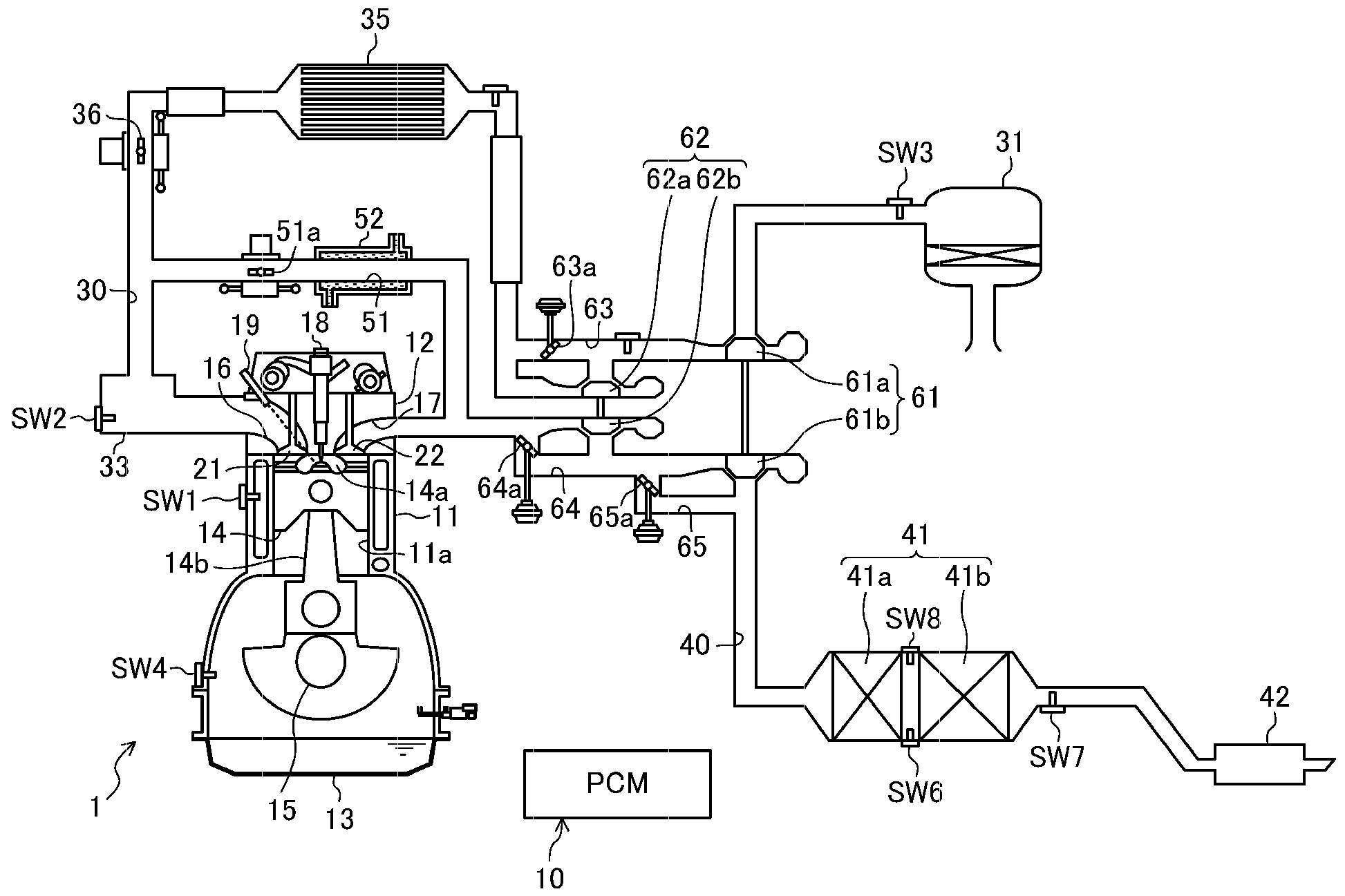
[0033] figure 1 A schematic configuration of an engine (engine main body) 1 according to the embodiment is shown. This engine 1 is a diesel engine mounted on a vehicle and supplied with fuel mainly composed of light oil. The cylinder head 12 and the oil pan 13 arranged on the lower side of the cylinder block 11 to store lubricating oil. A reciprocating piston 14 is inserted into each cylinder 11 a of the engine 1 , and a chamber defining a reentrant combustion chamber 14 a is formed on the top surface of the piston 14 . The piston 14 is connected to a crankshaft 15 via a connecting rod 14b.

[0034] In the above-mentioned cylinder head 12, an intake port 16 and an exhaust port 17 are formed for each cylinder 11a, and intake ports 16 and exhaust ports 17 are respectively ar...


PUM


Abstract

The invention provides a control device and a control method of a diesel engine. When the engine (1) is in a deceleration condition and when a predetermined DPF regeneration condition is satisfied, two opening controls for valve opening of an exhaust valve (22) during an intake stroke is performed (step S13) except for the opening of an intake valve (21) in the intake stroke and the opening of the exhaust valve (22) in the exhaust stroke of a cylinder.

Description

technical field [0001] The invention belongs to the technical field related to the control device of the diesel engine. Background technique [0002] A diesel engine in which a diesel particulate filter (Diesel particulate filter; hereinafter referred to as “DPF”) is provided in an exhaust passage is well known from the prior art. This DPF traps particulate matter (PM: Particulate matter) in exhaust gas, and regeneration is required when the accumulation of particulate matter increases. A catalyst having an oxidation function, for example, an oxidation catalyst is generally provided upstream of such a DPF, and this catalyst is used for regeneration of the DPF. For example, in a diesel engine according to Japanese Patent Laid-Open No. 2004-316441, after main injection of injecting fuel for generating torque is performed in a cylinder, after injection is performed, thereby introducing fuel in an unburned state into the exhaust passage . When the unburned fuel reaches the ca...

Claims


Application Information

Patent Timeline
IPC IPC(8): F02D43/00
CPCF02D41/029F02D41/123F02D41/405F02D2200/0802Y02T10/40F01N9/002F01N9/00
Inventor 西村博幸
Owner MAZDA MOTOR CORP
Why Eureka
Try Eureka