Distributed fiber leakage monitoring system of LNG storage tank

A technology of distributed optical fiber and monitoring system, which is applied in the method of container discharge, gas/liquid distribution and storage, container filling method, etc. It can solve the problem of inability to effectively reduce the environmental pollution and safety risks of LNG storage tanks, and it is difficult to determine the leakage point Accurate location, LNG storage tank can not meet the requirements and other problems, to achieve the effect of convenient long-distance transmission, convenient query, intrinsic explosion-proof

Active Publication Date: 2013-07-03
PIPECHINA SOUTH CHINA CO
View PDF6 Cites 12 Cited by
  • Summary
  • Abstract
  • Description
  • Claims
  • Application Information

AI Technical Summary

Problems solved by technology

The current method has the problems of too few temperature monitoring points, low detection accuracy, and the inability to detect a small amount of LNG leakage in time, and it is difficult to determine the exact location of the leakage point. In addition, it is impossible to alarm at the initial stage of LNG leakage, which is very easy cause serious secondary disasters
Therefore, using thermocouples, combustible gas detectors and flame ion detectors to monitor the leakage of LNG storage tanks has poor technical safety assurance, and cannot effectively reduce the environmental pollution and safety risks caused by the leakage of LNG storage tanks.
[0003] CN102242870A discloses a distributed optical fiber leakage monitoring device for pipelines, but it is only suitable for pipelines, and cannot meet the requirements for LNG storage tanks

Method used


Image

  • Distributed fiber leakage monitoring system of LNG storage tank
  • Distributed fiber leakage monitoring system of LNG storage tank
  • Distributed fiber leakage monitoring system of LNG storage tank

Examples


Embodiment

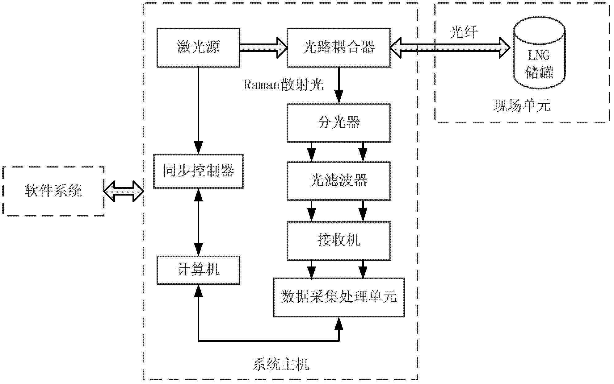
[0021] Example. This example is a test prototype of a distributed optical fiber leakage monitoring system for a 1000 square meter LNG storage tank. The principle block diagram is as figure 1 Shown.

[0022] The system is composed of a leakage monitoring system host and a distributed optical fiber on site. The system host includes a laser source, an optical path coupler, an optical splitter, an optical filter, a receiver, a data acquisition and processing unit, a synchronization controller and a computer; the laser emitted by the laser source is shot on the optical path coupler, and the optical path coupler is connected to the scene by an optical fiber The distributed optical fiber is connected to the optical splitter by the wire at the same time. After the optical splitter, the optical filter, the receiver, and the data acquisition and processing unit are connected in series. The data acquisition and processing unit has input and output connections with the computer; the laser so...


PUM


Abstract

The invention relates to a distributed fiber leakage monitoring system of a LNG storage tank. The invention relates to the technical fields of mechanical oscillation measurement, impact measurement and pipe-line system. The distributed fiber leakage monitoring system is composed of a leakage monitoring system host and an on-site distributed fiber, the on-site distributed fiber is paved in a heat-insulation layer between an inner pot base plate and an outer pot base plate of the LNG storage tank, and the heat-insulation layer between the inner pot wall and the outer pot wall; the system host (1) arranged at the far position of the LNG storage tank is connected to a fiber optic closure (5) outside the top of the LNG storage tank through a communication fiber (2), and the fiber optic closure (5) is connected to a pot wall monitoring fiber (3) and a pot bottom monitoring fiber (4). The distributed fiber leakage monitoring system has high safe technology and high protection performance, and can effectively reduce the environmental pollution and safety risk brought by the leakage of the LNG storage tank.

Description

Technical field [0001] The invention is a distributed optical fiber leakage monitoring system for LNG storage tanks. It involves the technical fields of mechanical vibration measurement, impact measurement and piping system technology. Background technique [0002] LNG storage tanks are important facilities for LNG receiving stations. At present, all the full-capacity LNG storage tanks built in my country adopt thermocouples, combustible gas detectors, flame ion detectors, etc. to monitor the LNG leakage of the storage tanks. Install 8 thermocouples on the wall and bottom of the full-capacity LNG storage tank, and judge whether there is a leak based on the temperature measured by the thermocouple; at the same time, install a combustible gas detector and flame ion on the top and outer wall of the LNG storage tank The detector is used to monitor the natural gas generated by gasification after LNG leakage and the flame ion generated by natural gas combustion. The current method h...

Claims


Application Information

Patent Timeline
Patent Type & Authority Applications(China)
IPC IPC(8): F17C13/02
Inventor 许斌谭东杰王立坤吴家勇王洪超周琰胡森刘冰彭世垚余东亮陈英杰
Owner PIPECHINA SOUTH CHINA CO
Why Eureka
Try Eureka