
Coplanar waveguide feed directional diagram reconfigurable planar monopole antenna

A technology of monopole antenna and coplanar waveguide, which is applied in the direction of antenna, antenna grounding device, electrical components, etc., can solve the problems of narrow antenna working bandwidth and adverse effects of antenna radiation performance, and achieve high isolation, light weight, and low The effect of bad influence

Inactive Publication Date: 2013-07-03
SOUTH CHINA UNIV OF TECH
View PDF5 Cites 2 Cited by
  • Summary
  • Abstract
  • Description
  • Claims
  • Application Information

AI Technical Summary

Problems solved by technology

Of course, due to the immature development of pattern reconfigurable antennas, in some existing pattern reconfigurable antenna technologies, there are still problems with narrow antenna operating bandwidth and poor linearity due to the use of PIN or FET RF switches. The problem of switching and thus adversely affecting the radiation performance of the antenna

Method used


Image

  • Coplanar waveguide feed directional diagram reconfigurable planar monopole antenna
  • Coplanar waveguide feed directional diagram reconfigurable planar monopole antenna
  • Coplanar waveguide feed directional diagram reconfigurable planar monopole antenna

Examples


Embodiment Construction

[0019] The embodiments of the present invention will be described in detail below with reference to the drawings: this embodiment is implemented on the premise of the technical solution of the present invention, and detailed implementation modes and specific operation procedures are given, but the protection scope of the present invention is not limited to the following Mentioned examples.

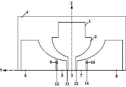
[0020] Such as figure 1 As shown, the example of the present invention provides a coplanar waveguide-fed directional pattern reconfigurable planar monopole antenna including: a dielectric substrate 4 and a rectangular radiating patch 1, a semicircular radiating patch located on the top surface of the dielectric substrate 4 Sheet 2, coplanar waveguide feeder line 3, first coplanar waveguide floor 5, second coplanar waveguide floor 6, third coplanar waveguide floor 7, fourth coplanar waveguide floor 8, first MEMS switch 9, second MEMS Switch 10. There is a first gap 11 between the coplanar wav...


PUM


Abstract

The invention discloses a coplanar waveguide feed directional diagram reconfigurable planar monopole antenna, which comprises a metal coating, two micromechanical system (MEMS) switches and a medium substrate. The metal coating comprises a radiation patch, a coplanar waveguide feeder line and a coplanar waveguide floor. The coplanar waveguide floor comprises a first coplanar waveguide floor, a second coplanar waveguide floor, a third coplanar waveguide floor and a fourth coplanar waveguide floor. The coplanar waveguide feed directional diagram reconfigurable planar monopole antenna is simple in structure, the state of the coplanar waveguide floor can be effectively changed only by controlling the on-off of a first MEMS switch and a second MEMS switch, therefore, the reconfiguration purpose of an antenna radiation directional diagram can be realized on the premise of maintaining the working frequency. The antenna is used for transmitting and receiving electromagnetic waves and has the characteristics of small size, light weight, convenience in machining and wide working band.

Description

Technical field [0001] The invention relates to a pattern reconfigurable antenna in the field of wireless communication, and in particular to a pattern reconfigurable planar monopole antenna fed by a coplanar waveguide. Background technique [0002] With the development and advancement of science and technology, people’s demand for wireless communication is increasing, and a variety of new communication methods are emerging in an endless stream. The design of antenna modules is also facing increasing requirements and challenges. Reconfigurable antennas are naturally proposed and obtained. It has become more and more extensive and in-depth development. At present, the wireless communication system is developing in the direction of diversified functions, miniaturization, modularization, and strong adaptability to different communication environments. As an indispensable part of the wireless communication system, the antenna module is bound to have flexible and diverse radiation pe...

Claims


Application Information

Patent Timeline
IPC IPC(8): H01Q1/38H01Q1/48H01Q3/24
Inventor 胡斌杰黄俊杰
Owner SOUTH CHINA UNIV OF TECH
Learn More